
 |


23HS8440-23
Zhong Hua Jiang
2.4V
4A
76mm

Zhong Hua Jiang 23HS8440-23 is a 57mm NEMA 23 two-phase hybrid stepper motor for industrial CNC positioning and automated motion systems. The published model information specifies a 1.8° full-step angle, 2.4V rated phase voltage, 4.0A rated phase current and 76mm motor length. Its listed holding torque is around 1.9 N·m; confirm the approved torque-speed characteristic for the intended axis before final selection.
The 57mm frame is commonly classified as NEMA 23. The term “57 stepper motor” refers to the approximate metric frame size and should not be confused with a separate NEMA 57 frame standard. Mechanical fit must be checked against the supplied dimensional drawing.
| Item | Specifications |
|---|---|
| Number of Phases | 2 |
| Step Angle | 1.8° (listed accuracy ±5%) |
| Rated Voltage | 2.4V |
| Rated Current | 4.0A |
| Resistance | 0.6 Ω ±10% at 20°C |
| Inductance | 2.2 mH ±20% at 1 kHz, 1 Vrms |
| Holding Torque | Above 1.9 N·m (as published) |
| Detent Torque | Below 6.0 N·cm (as published) |
| Rotor Inertia | 480 g.cm² |
| Lead Style | AWG22 UL1007 |
| Insulation Class | Class B |
| Dielectric Strength | 500V AC for 1 minute |
| Insulation Resistance | Above 100 MΩ (as published) |
| Allowable Thrust Load | 15N |
| Allowable Radial Load | 75 N at shaft end |
The general specification lists holding torque as above 1.9 N·m. Holding torque is measured under specified energized conditions; it is not a continuous running-torque guarantee.
Request Price and 23HS8440-23 Specifications
For OEM comparison, use the manufacturer-listed electrical data for model 23HS8440-23. The nominal 2.4V value describes the motor winding at rated current, not a fixed input requirement for a stepper driver. Select a current-regulated two-phase driver and set its current according to the motor and driver documentation.
| Model No. | Step Angle | Motor Length | Voltage | Current | Resistance | Inductance | Holding Torque | Inertia | Lead Style |
|---|---|---|---|---|---|---|---|---|---|
| (°) | (L)mm | V | A | Ω | mH | N·m | g.cm² | # | |
| 23HS8440-23 | 1.8 | 76 | 2.4 | 4.0 | 0.6 | 2.2 | 1.9 | 480 | AWG26 1061 |
Lead-wire details in the supplied technical information include AWG26 1061 and AWG22 UL1007. Buyers should verify the actual lead gauge, insulation designation, wire colors, connector and cable length against an approved drawing before procurement or assembly.
The published nominal holding-torque entry is 1.9 N·m. For design acceptance and replacement sourcing, request the manufacturer-issued motor datasheet and torque-speed information for this exact model.
| Insulation Level | Insulation Voltage | Insulation Resistance |
|---|---|---|
| Class B | 500V A.C 1 Minute | Above 100 MΩ |
| Class F | 500V A.C 1 Minute | Above 100 MΩ |
The 23HS8440-23 is listed with Class B insulation. Class F is shown for general comparison. A different insulation class should not be assumed for the 23HS8440-23 without a confirmed model-specific specification.
Insulation systems are categorized by thermal endurance. The following published chart is provided for interpreting standard A, E, B, F and H class designations; it does not mean that every insulation class is supplied for this particular model.
| Temperature class of insulation | A Level | E Level | B Level | F Level | H Level |
|---|---|---|---|---|---|
| Maximum allowable temperature (℃) | 105 | 120 | 130 | 155 | 180 |
| Winding temperature rise limit (K) | 60 | 75 | 80 | 100 | 125 |
| Performance reference temperature (℃) | 80 | 95 | 100 | 120 | 145 |
Ask About Motor Windings and Driver Matching

The product listing states a 76mm motor length for model 23HS8440-23. Review the mounting-hole pattern, pilot diameter, shaft length, shaft diameter and overall envelope in the dimension drawing before specifying a mounting bracket, coupling or replacement assembly.
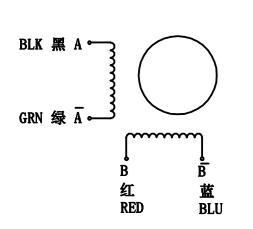
The diagram above provides a connection reference. Identify the two coil pairs using the approved lead-color chart or continuity testing before connecting a driver. Do not determine winding polarity solely from image colors without confirming the supplied motor configuration.
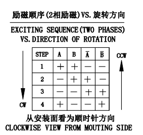
The excitation-sequence diagram illustrates two-phase drive logic. Actual microstepping and current regulation are handled by the selected stepper driver; direction, pulse input and phase wiring must match the controller and driver configuration.
Request Dimension Drawing and Wiring Details
| Step Angle Accuracy | ±5% |
|---|---|
| Resistance Accuracy | ±10% |
| Inductance Accuracy | ±20% |
| Temperature Rise | 80°C Max. |
| Ambient Temperature | -20°C~+50°C |
| Insulation Resistance | 100MΩ Min 500V DC |
| Dielectric strength | 500V AC 1 Minute |
| Allowable Radial Load | 75N |
| Allowable Thrust Load | 15N |
Choose a bipolar two-phase stepper driver with an appropriate current rating and a supply voltage within the driver manufacturer’s permitted range. A winding voltage of 2.4V is not the same as the DC bus voltage used by a current-limiting chopper driver. Match current settings, coil connection, thermal conditions and supply limits to the complete motor-drive system.
Holding torque describes static shaft resistance while the motor is energized at specified conditions. Available torque usually changes with speed, current settings, bus voltage, winding inductance and load inertia. For high-speed CNC axes, verify the torque-speed curve and allow an engineering margin for acceleration and external forces.
This 57mm hybrid stepper motor can be evaluated for CNC router positioning axes, automated feed systems, indexing mechanisms, packaging equipment and other controlled-motion assemblies. Suitability depends on load torque, speed, duty cycle, mounting, environmental temperature and driver integration.
For an accurate quotation, specify the required quantity, application, operating speed, load profile, mounting dimensions, shaft design, lead or connector type, driver information and destination market. Confirm any project-specific documentation or compliance requirements for the exact motor configuration.
Request an OEM Stepper Motor Quotation


Huajiang began manufacturing CNC engraving spindle motors in 2000 and later expanded its activities into variable frequency drives (VFDs) and engraving equipment. The Zhong Hua Jiang brand was established in 2018 to serve the company’s wider market.
The company also references a registered patent related to its air-cooled spindle-motor range, Patent No. 200730184245.5. This patent pertains to that spindle product family and should not be interpreted as a patent covering this stepper motor.
For motor sourcing and project evaluation, buyers may discuss technical specifications, replacement fit and purchasing requirements with the sales team.
| Quality Assurance Superior quality performance Strict quality control | Patents and Certifications Several patents for air-cooled spindle motors | Additional Brand Value Brand value highly recognized by the market |
| Reasonable Price Direct factory sales Highly cost performance | Full time Service Professional technical support Close and quick customer service | Fast and Reliable Delivery Fast and efficient delivery system Real-time tracking and updates |

Zhong Hua Jiang supplies equipment and components for CNC machinery applications, with product information designed to support engineering selection, service and purchasing discussions.
The company’s manufacturing history dates to 2000. For 23HS8440-23 orders, request current model drawings, traceable specifications and quotation details appropriate to the intended industrial application.

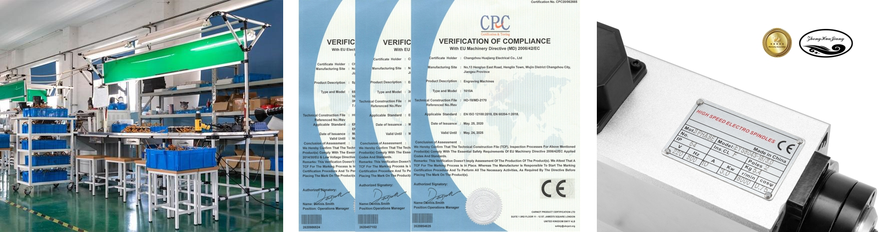
Company documentation is shown above. For engineering or procurement approval, check each certificate’s issuing organization, scope and validity against the actual document. Ask for records specifically applicable to the motor or purchase order where required.
It is a 57mm-frame motor generally described by the NEMA 23 frame category. The “57” label refers to an approximate metric face size; use actual mounting dimensions for interchangeability.
The published motor specification lists 2.4V as its rated phase or winding voltage. This must not be mistaken for a 24V winding rating or treated as the required stepper-driver DC supply.
The listed phase current is 4.0A and the phase resistance is 0.6 Ω ±10% at 20°C.
Its nominal full-step angle is 1.8°, equivalent to 200 full steps per mechanical revolution before microstepping.
The published holding torque is around 1.9 N·m. Confirm the model-specific test conditions; holding torque should not be used as a running-torque figure.
The product-specific electrical table identifies a 76mm motor length. Check the dimension drawing for the total installed envelope including shaft and wiring.
Use a two-phase, current-regulated driver that supports the required 4.0A motor phase current, with driver current-setting conventions and operating temperature taken into account. The driver model should be verified for the application.
A properly configured current-limited stepper drive may use a higher DC bus voltage, subject to the driver and motor specifications. Do not connect a higher-voltage supply directly to the winding without current regulation.
The listed phase inductance is 2.2mH ±20%, measured at 1kHz and 1Vrms. Inductance is one input for estimating high-speed performance with a given driver.
It can be evaluated for CNC positioning systems where its frame size, running torque, acceleration, mechanical coupling and driver match the axis requirements. Verify the torque-speed curve under the intended conditions.
The nominal frame category is NEMA 23, but mounting hole positions, pilot fit, shaft geometry and body envelope must be matched to the actual engineering drawing.
Technical information references AWG22 UL1007 and AWG26 1061 lead designations. Confirm the cable construction for the ordered configuration, together with connector type and pinout.
Use the approved wiring diagram or measure continuity between conductors. Do not energize wires based only on assumptions about color or sequence.
The general specification lists Class B. The separate insulation chart compares several thermal classes and does not establish that all those variants are available for this model.
The technical-conditions table states an ambient range from -20°C to +50°C and a temperature-rise figure of 80°C maximum. Confirm the test setup and practical cooling arrangement for your duty cycle.
The allowable thrust load is listed as 15N and the radial load as 75N at the shaft end. Verify the measurement conditions and any belt, gear or lead-screw side load before design approval.
Potential applications include robotic positioning, indexing tables and automation axes, subject to verified torque, speed, load inertia, resonance and driver compatibility.
Provide model 23HS8440-23, planned quantity, equipment use, speed and load requirements, shaft and mounting specifications, lead configuration, driver model and applicable documentation needs.
Please request the current documentation required for your project and verify that the certificate scope and drawing revision match the actual motor supplied.
Send your target quantity, destination country, packaging or labeling requirements and application details using the contact page. The sales team can review the specification and quotation request.


