
 |


16HS2404L14.5P1-X
Zhong Hua Jiang
8.4V
0.42A
20mm
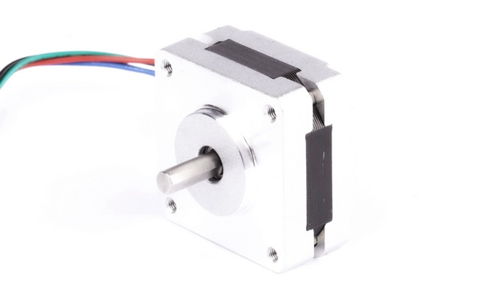
The Zhong Hua Jiang 16HS2404L14.5P1-X is a compact 39mm-frame, 2-phase hybrid stepper motor designed for precise incremental motion in CNC equipment, 3D printers, robotics, automation systems, positioning mechanisms and other motion-control applications. It uses a 1.8° full-step angle, equal to 200 full steps per revolution before microstepping.
The motor is specified at 8.4V and 0.42A per phase with 20Ω phase resistance, 17mH inductance, Class B insulation and AWG26 lead wires. Its 39mm square frame corresponds to the NEMA 16 size commonly used for compact motion systems where a smaller footprint is required.
Request 16HS2404L14.5P1-X Pricing
| Item | Specifications |
| No. of Phases | 2 |
| Step Angle | 1.8° ±5% |
| Rated Voltage | 8.4V |
| Rated Current | 0.42A |
| Resistance | 20Ω ±10% at 20°C |
| Inductance | 17mH ±20% at 1kHz, 1Vrms |
| Holding Torque | Above 0.09 N·m |
| Detent Torque | Below 0.5 N·cm max. |
| Rotor Inertia | 11 g·cm² |
| Lead Style | AWG26 UL1007 |
| Insulation Class | Class B |
| Dielectric Strength | 500V AC for 1 minute |
| Insulation Resistance | Above 100MΩ |
| Allowable Thrust Load | 10N |
| Allowable Radial Load | 21N at shaft end |
With a 1.8° step angle, the motor provides 200 full steps per revolution. When used with a compatible current-controlled microstepping driver, the electrical step can be subdivided to improve motion smoothness and reduce low-speed vibration. Actual positioning performance depends on the driver, controller, mechanical transmission, acceleration profile, resonance and applied load.
Ask About Driver Compatibility
| Model No. | Step Angle | Motor Length | Voltage | Current | Resistance | Inductance | Holding Torque | Inertia | Lead Style |
| (°) | (L) mm | V | A | Ω | mH | mN·m | g·cm² | # | |
| 16HS2404L14.5P1-X | 1.8 | 20 | 8.4 | 0.42 | 20 | 17 | 9 | 11 | AWG26 1061 |
The electrical table above reproduces the representative product data from the original page. Products with special requirements can be discussed according to the customer's electrical, mechanical, lead-wire and application requirements.
Technical note: the original page contains two different holding-torque entries. The general specification lists “Above 0.09 N·m,” while the electrical specification table lists “9 mN·m.” Because these values are not equivalent, confirm the latest engineering datasheet before using holding torque as a design value.
| Insulation Level | Insulation Voltage | Insulation Resistance |
| Class B | 500V AC, 1 minute | Above 100MΩ |
| Class F | 500V AC, 1 minute | Above 100MΩ |
The insulation class describes the heat-resistance category of the motor winding insulation system. The general specification for the 16HS2404L14.5P1-X identifies this model as Class B.
| Temperature Class of Insulation | A Level | E Level | B Level | F Level | H Level |
| Maximum Allowable Temperature (°C) | 105 | 120 | 130 | 155 | 180 |
| Winding Temperature Rise Limit (K) | 60 | 75 | 80 | 100 | 125 |
| Performance Reference Temperature (°C) | 80 | 95 | 100 | 120 | 145 |
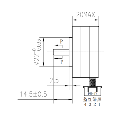
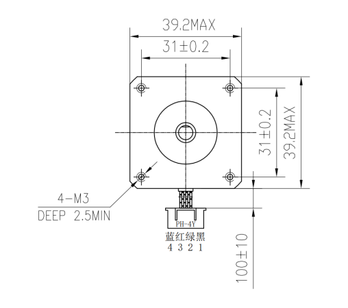
Before replacing an existing motor or integrating the 16HS2404L14.5P1-X into a new motion system, compare the frame size, mounting-hole spacing, shaft dimensions, body length and available installation envelope with the mechanical drawings. Mechanical compatibility should be verified independently from the product naming convention.
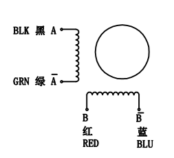
Connect the motor phases to the corresponding A and B outputs of a compatible bipolar stepper driver. Confirm the coil pairs before applying power and disconnect power before changing motor wiring.
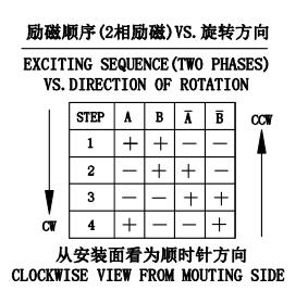
The driver energizes the motor phases in sequence to create controlled angular movement. Full-step, half-step and microstepping operation depend on the selected driver and controller. Correct phase-current limiting is important for motor temperature, available torque and service life.
| Step Angle Accuracy | ±5% |
| Resistance Accuracy | ±10% |
| Inductance Accuracy | ±20% |
| Temperature Rise | 80°C max. |
| Ambient Temperature | -20°C to +50°C |
| Insulation Resistance | 100MΩ min. at 500V DC |
| Dielectric Strength | 500V AC, 1 minute |
| Allowable Radial Load | 21N |
| Allowable Thrust Load | 10N |
These tolerances and operating conditions should be considered as part of the complete motion-system design. Running torque normally changes with motor speed, driver current, supply voltage, acceleration and load inertia, so final selection should be based on the required operating point rather than holding torque alone.
The 39mm 2-phase hybrid stepper motor can be considered for compact CNC mechanisms, 3D printers, robotics, automation equipment, positioning stages, test fixtures, dispensing systems, optical positioning equipment and other applications that require repeatable incremental movement.
For motor selection, provide the required speed range, load torque, acceleration, duty cycle, load inertia, shaft load, mechanical dimensions, driver model, supply voltage and order quantity. These details help determine whether the 16HS2404L14.5P1-X or another stepper motor configuration is more suitable.
A 39mm-frame motor fits between smaller 35mm-class motors and common 42mm NEMA 17 motors. This frame size can be useful when the machine requires a compact mounting envelope while still needing the controlled positioning characteristics of a 2-phase hybrid stepper motor.


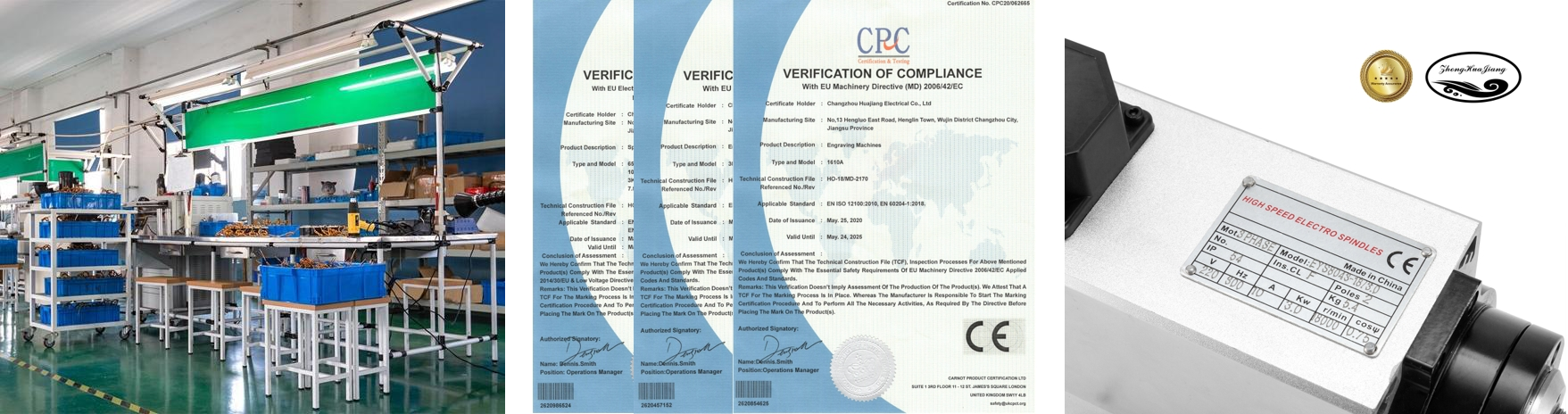
Huajiang was founded in 2000, beginning with the production of CNC engraving spindle motors and later expanding into variable-frequency drives, engraving machines and related CNC products. To support broader market development, the Zhong Hua Jiang brand was established in 2018.
The company has a registered patent for a series of air-cooled spindle motors, patent No. 200730184245.5, and more than 20 years of manufacturing experience in CNC-related products.
 | ||
| Quality Assurance Product inspection and quality-control procedures before shipment. | Patents and Certifications Manufacturing experience and patented air-cooled spindle designs. | Additional Brand Value Integrated product support for CNC, spindle and motion-control applications. |
 | ||
| Reasonable Price Direct factory communication for specifications, quantities and customization. | Full-Time Service Technical support for product selection and application questions. | Fast and Reliable Delivery Production coordination, export service and shipment updates. |

Certification requirements can vary by destination market and final equipment. For OEM or batch orders, request the current documentation required for your project and confirm the applicable compliance requirements before purchase.
The 16HS2404L14.5P1-X is a 39mm-frame motor. In standard stepper-motor frame terminology, a 39mm square frame is commonly classified as NEMA 16. Always confirm the mechanical drawing and mounting dimensions when replacing an existing motor.
A 1.8° full-step angle provides 200 full steps per revolution. A compatible microstepping driver can electronically subdivide each full step for smoother commanded motion.
The original product specification lists 8.4V rated voltage and 0.42A rated current. When a current-controlled stepper driver is used, configure the phase-current limit according to the motor and driver requirements.
Use a bipolar 2-phase stepper driver that can regulate phase current around the motor's 0.42A rating and is compatible with the available controller and power supply. Confirm the driver's current range, supply-voltage range, connector arrangement and microstep settings before installation.
Yes. A compatible microstepping driver can subdivide the motor's 1.8° full steps to improve smoothness and reduce vibration. Microstep resolution should not be treated as guaranteed mechanical positioning accuracy under load.
The original page contains two different values: the general specification lists holding torque above 0.09 N·m, while the electrical specification table lists 9 mN·m. Confirm the latest engineering datasheet with Zhong Hua Jiang before using holding torque as a design value.
The source specification lists an allowable radial load of 21N and an allowable thrust load of 10N. Couplings, pulleys, lead screws and belt arrangements should be designed so the motor shaft remains within the stated load limits.
Provide the current motor model, frame and shaft dimensions, mounting-hole spacing, load torque, target speed, acceleration, duty cycle, driver model, supply voltage, lead-wire requirements, connector requirements, quantity and final application.
The original product information states that products with special requirements can be made according to customer requests. Send the required electrical specifications, dimensions, shaft configuration, wiring, connector and order quantity for evaluation.


