Variable Frequency Drives (VFDs) are the backbone of CNC (Computer Numerical Control) machine operations, providing precise control over spindle motor speed, torque, and energy efficiency. For users of Zhong Hua Jiang VFDs, known for their reliability and precision, a fault code flashing on the display can be alarming, signaling issues that could disrupt machining tasks. These fault codes are diagnostic alerts designed to protect the system from damage due to electrical faults, overloads, or configuration errors. While Zhong Hua Jiang VFDs are robust, they require proper setup, maintenance, and troubleshooting to maintain optimal performance. This guide walks you through the most common fault codes, their causes, and step-by-step solutions to get your CNC system back on track. By understanding these codes and following systematic troubleshooting, you can minimize downtime and ensure smooth operation.
Importance of Addressing VFD Fault Codes
Fault codes on a Zhong Hua Jiang VFD (Variable Frequency Drive) serve as critical diagnostic alerts, signaling issues such as overcurrent, overvoltage, undervoltage, overheating, or sensor failures. These faults can halt CNC (Computer Numerical Control) operations, disrupt production, and potentially damage the spindle motor or other components if not addressed promptly. Understanding and resolving these fault codes is essential for maintaining the reliability, precision, and efficiency of your CNC system. Below, we outline the key reasons why immediate action is necessary and provide general guidelines for safe troubleshooting.
Why Prompt Diagnosis and Resolution Are Critical
Prevent Damage: Fault codes indicate conditions like excessive current, voltage spikes, or overheating that can stress or damage the VFD, spindle motor, or connected components. For example, an overcurrent fault (e.g., EoCH/OC) could result from a short circuit, which, if ignored, may burn out motor windings or VFD circuitry. Addressing faults quickly protects your equipment from costly repairs or replacements.
Minimize Downtime: CNC machines are often central to production workflows, and a fault can cause significant delays. Resolving issues promptly—such as resetting a fault or correcting wiring—keeps operations running smoothly, avoiding production bottlenecks and financial losses.
Maintain Precision: VFD faults can lead to inconsistent spindle performance, such as erratic speeds or torque, which compromise machining accuracy. Ensuring the VFD and spindle motor operate within their specified parameters maintains the tight tolerances and high-quality finishes required for applications like milling, engraving, or metalworking.
Safety and Preparation for Troubleshooting
Before attempting to diagnose or resolve any VFD (Variable Frequency Drive) fault on your Zhong Hua Jiang model, it is imperative to prioritize safety and follow a structured preparation process. Troubleshooting electrical systems like VFDs involves risks such as electrical shock, component damage, or even fire hazards if not handled correctly. These steps help mitigate those risks, ensure accurate diagnosis, and prevent worsening the issue. Always remember that VFDs deal with high voltages and currents, so err on the side of caution and seek professional help if you're not experienced with electrical systems.
1. Power Off the System
Always turn off the VFD and the entire CNC machine at the main power source before inspecting wiring, connections, or internal components. This includes disconnecting the power supply and allowing time for capacitors in the VFD to discharge (typically 5–10 minutes) to avoid residual voltage. This critical step prevents electrical shock, personal injury, or exacerbation of existing faults, such as short circuits or arcing. Verify the power is off using a voltage tester on the input terminals to confirm zero voltage before proceeding.
2. Consult the User Manual
Refer to the user manual for your specific Zhong Hua Jiang VFD model (e.g., H100 series) to confirm fault code definitions, parameter settings, and recommended troubleshooting procedures. Manuals provide model-specific guidance, as codes and parameters may vary slightly across versions or firmware updates. If the manual is digital, search for terms like "fault codes" or "error messages" for quick reference. This ensures you interpret the code correctly and avoid unnecessary adjustments that could lead to further issues.
3. Contact the Supplier if Needed
If you lack the manual, are unsure about a fault code, or encounter an unfamiliar error, reach out to the VFD supplier or manufacturer for support. Zhong Hua Jiang VFDs may share similarities with Huanyang models (common rebrands in the CNC market), so cross-referencing Huanyang manuals (available online via forums, supplier websites, or PDF downloads) can be helpful if documentation is unavailable. Provide details like the model number, fault code, and symptoms to get accurate advice, potentially saving time and preventing misdiagnosis.
4. Use Proper Tools
Equip yourself with diagnostic tools like a multimeter (for measuring voltage, current, and continuity), megohmmeter (for testing insulation resistance), thermal imager (for detecting hot spots indicating overheating), or vibration analyzer (for assessing mechanical issues like bearing wear). These tools allow for accurate assessment of electrical and mechanical issues without guesswork. Ensure tools are calibrated and rated for the voltages involved (e.g., CAT III or higher for industrial use) to avoid inaccurate readings or safety risks.
5. Follow Safety Protocols
Wear appropriate personal protective equipment (PPE), such as insulated gloves, safety glasses, and non-conductive footwear, to protect against electrical hazards. Ensure the work area is dry, well-lit, and free of hazards like flammable materials or clutter that could cause accidents. Ground yourself if working with static-sensitive components, and never bypass safety interlocks on the CNC machine. If the fault involves high-voltage components, consider involving a certified electrician to comply with local electrical codes and standards.
By adhering to these safety and preparation steps, you create a secure environment for troubleshooting, reduce the risk of personal injury or equipment damage, and increase the likelihood of a successful resolution. Once prepared, proceed to identifying the specific fault code (e.g., E.oc for overcurrent) and follow targeted troubleshooting as outlined in subsequent sections. If the issue persists after basic checks, professional servicing may be required to avoid voiding warranties or causing irreversible damage.
Common Zhong Hua Jiang VFD Fault Codes and Their Solutions
Zhong Hua Jiang Variable Frequency Drives (VFDs), commonly used in CNC (Computer Numerical Control) machines to control spindle motor speed and torque, are equipped with a diagnostic system that displays fault codes on the LED screen when issues arise. These codes—such as E.oc, E.ou, E.Lu, and others—pinpoint specific problems like overcurrent, overvoltage, or grounding faults, enabling operators to address issues before they cause significant damage or downtime. Below, we detail the most common fault codes for Zhong Hua Jiang VFDs (e.g., H100 series, often similar to Huanyang models), their causes, and step-by-step solutions. Always power off the VFD and CNC system before troubleshooting to avoid electrical hazards, and consult the user manual for model-specific details. If a fault persists or involves internal VFD components, seek professional assistance to prevent further damage or voiding warranties.
1. E.oc (Overcurrent During Running)

The E.oc fault indicates excessive current draw during operation, triggering the VFD to shut down to protect the spindle motor and itself. This is a common issue in CNC applications due to electrical or mechanical problems.
Common Causes
Short circuit or insulation failure in the motor or wiring.
Sudden load changes, such as tool binding or excessive cutting depth.
Incorrect acceleration settings causing current spikes.
Overboosted torque or improper DC braking settings.
Unstable power supply voltage.
Solutions
Check for Short Circuits or Insulation Issues
Use a multimeter to test continuity and a megohmmeter to check insulation resistance (>1 MΩ) between motor terminals (U, V, W) and ground. Inspect wiring for frayed, pinched, or loose connections, ensuring a shielded 4-wire cable (including ground) is used.
Ensure Motor Isn’t Jammed or Overloaded
Manually rotate the spindle to confirm it moves freely. Verify that the tool or workpiece isn’t causing excessive load (e.g., overly deep cuts or improper tool size).
Increase Acceleration/Deceleration Time
Adjust PD014 (acceleration time) and PD015 (deceleration time) to higher values (e.g., 5–10 seconds) to reduce current spikes during speed changes.
Reduce DC Braking or Torque Boost
Lower PD061 (DC braking amount) or PD009 (torque boost) if set too high, as excessive settings can trigger overcurrent faults.
Stabilize Power Supply Voltage
Use a multimeter to verify input voltage (e.g., 220V ±15% or 380V) is stable. Install a surge protector or voltage stabilizer if fluctuations are detected.
Reset and Retest
Clear the fault by pressing the STOP/RESET button, then restart. If the fault persists, test motor windings for balanced resistance (U-V, V-W, U-W) and consult a technician for potential VFD or motor damage.
Preventive Measures
Use shielded cables to minimize electromagnetic interference (EMI).
Set parameters (PD141, PD142, PD144) to match the spindle’s voltage, power, and RPM.
Regularly inspect motor and wiring for wear or insulation degradation.
2. E.ou (Overvoltage During Running)

The E.ou fault signals excessive voltage in the VFD’s DC bus, often during deceleration, causing a protective shutdown.
Common Causes
Rapid deceleration causing regenerative voltage buildup.
Voltage spikes or instability in the power supply.
Missing or faulty braking resistor for high-inertia loads.
Solutions
Extend Deceleration Time
Increase PD015 (deceleration time) to 5–10 seconds to allow smoother slowdown, reducing regenerative voltage.
Add or Check Braking Resistor
For high-inertia spindles (e.g., heavy-duty milling), install an external braking resistor as specified in the manual and verify its connection and resistance value. Replace if faulty.
Check Power Line Voltage
Use a multimeter to confirm input voltage stability (e.g., 220V ±15%). Install a surge protector or power conditioner to mitigate spikes.
Inspect DC Bus
If equipped, measure DC bus voltage (consult manual for safe limits). Persistent overvoltage may indicate internal VFD issues, requiring professional repair.
Reset and Retest
Clear the fault and test with adjusted settings. If unresolved, contact the VFD supplier for further diagnostics.
Preventive Measures
Use a braking resistor for applications with frequent or rapid deceleration.
Monitor power supply stability and use protective devices.
Schedule regular checks of deceleration settings for high-inertia tasks.
3. E.Lu (Low Voltage Fault)

The E.Lu fault indicates insufficient input or DC bus voltage, preventing normal VFD operation.
Common Causes
Low network voltage (e.g., below 200V for a 220V VFD).
Power interruptions, brownouts, or loose connections.
Faulty internal VFD power components.
Solutions
Inspect Power Supply
Use a multimeter to measure input voltage at terminals (R, S, T), ensuring it matches the VFD’s rated voltage (e.g., 220V ±15%). Address low voltage with a voltage stabilizer or uninterruptible power supply (UPS).
Check Power Connections
Inspect input terminals for loose, corroded, or damaged connections. Tighten or replace as needed.
Monitor for Interruptions
Verify no power drops occur during operation, especially in facilities with heavy electrical loads. Use a dedicated power line if necessary.
Reset and Retest
Clear the fault and restart. If the fault persists, send the VFD for professional repair, as internal components like capacitors may be faulty.
Preventive Measures
Install a voltage stabilizer or UPS to maintain consistent power.
Use a dedicated circuit for the VFD to avoid interference.
Regularly inspect power cables for wear.
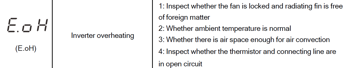
4. E.oH (Inverter Overheating)

The E.oH fault signals excessive temperature in the VFD or spindle motor, triggering a shutdown to prevent thermal damage.
Common Causes
Blocked ventilation or clogged cooling fans/fins.
High ambient temperatures exceeding VFD specifications (e.g., >40°C).
Faulty cooling fan or thermistor.
Solutions
Clean Heat Sink and Fan
For air-cooled VFDs, use compressed air to clean cooling fins and fans, removing dust or debris that obstructs airflow.
Ensure Proper Ventilation
Verify the VFD has 10–15 cm clearance around it and is in a well-ventilated area. Install external fans or air conditioning if ambient temperatures are high.
Check Spindle Cooling
For water-cooled spindles, confirm coolant levels and flow. Flush the system if clogged and inspect for leaks.
Inspect Cooling Components
Test the VFD’s cooling fan for operation and replace if faulty. Use a thermal imager to check for hot spots, which may indicate a defective thermistor.
Reduce Load if Needed
Ensure the spindle isn’t overloaded by reviewing cutting parameters and material demands.
Preventive Measures
Install the VFD in a dust-free, climate-controlled environment (0–40°C).
Clean cooling components monthly or every 500 operating hours.
Monitor ambient conditions and spindle load to avoid overheating.
5. E.FoP (Power Tube Protection)
The E.FoP fault indicates a fault in the VFD’s power transistors (IGBTs), often due to a short circuit or overload condition.
Common Causes
Short circuit in the motor or output wiring.
Faulty insulation in the output line.
Internal VFD component failure.
Solutions
Inspect Motor and Output Line
Test motor windings and output cables (U, V, W) for short circuits or ground faults using a megohmmeter (>1 MΩ) and multimeter.
Verify Wiring Integrity
Ensure no loose or damaged connections between the VFD and spindle. Replace faulty cables.
Contact Service Center
If no external faults are found, the issue likely involves internal VFD components (e.g., IGBT module). Send the unit for professional repair, as internal fixes require specialized equipment.
Preventive Measures
Use high-quality, shielded cables for motor connections.
Regularly test insulation resistance to catch degradation early.
Avoid overloading the VFD beyond its rated capacity.
6. E.GFF (Short Circuit to Ground)

The E.GFF fault indicates a grounding issue or short circuit between the motor or wiring and ground, posing a serious risk of damage.
Common Causes
Damaged insulation in motor windings or cables.
Improper grounding of the VFD or motor.
Moisture or contamination causing conductive paths.
Solutions
Check Insulation
Use a megohmmeter to test insulation resistance between motor terminals (U, V, W) and ground (>1 MΩ). Replace the motor or cables if insulation is compromised.
Inspect Grounding
Ensure the VFD and spindle motor are properly grounded with a dedicated ground wire. Check for loose or corroded ground connections.
Address Environmental Factors
Remove moisture or contaminants (e.g., coolant, dust) from the motor or wiring. Use sealed enclosures or conduit for protection.
Seek Professional Repair
If the fault persists, contact a technician, as the issue may involve internal VFD damage or severe motor failure.
Preventive Measures
Use sealed, IP-rated enclosures to protect against moisture and dust.
Regularly inspect grounding connections and insulation integrity.
Maintain a clean operating environment to prevent contamination.
7. E.oLd (Inverter Overload, 150% for 1 Minute)

The E.oLd fault indicates the VFD is operating beyond its rated capacity (e.g., 150% of rated current for 1 minute), triggering a shutdown.
Common Causes
Excessive load on the inverter due to heavy cutting or improper settings.
Mechanical issues causing the motor to work harder (e.g., locked rotor).
Incorrect V/F (voltage/frequency) curve settings.
Solutions
Upgrade Inverter Capacity
If the workload consistently exceeds the VFD’s rating, replace it with a higher-capacity model (e.g., upgrade from 2.2 kW to 3.7 kW).
Check for Mechanical Load
Inspect the spindle for jamming or excessive resistance. Ensure cutting parameters (e.g., depth, feed rate) are within the motor’s capabilities.
Reset V/F Settings
Adjust PD011 (V/F curve) or related parameters to match the motor’s requirements. Reset to factory defaults (PD013=08) if settings are incorrect.
Test Motor and Load
Verify motor condition with a multimeter and ensure the workload is appropriate for the motor’s power rating.
Preventive Measures
Match VFD and motor capacities to the application’s demands.
Optimize cutting parameters to avoid overloading.
Schedule regular mechanical inspections to prevent jams or excessive loads.
8. E.oLL (Motor Overload, 150% for 1 Minute)

The E.oLL fault signals that the spindle motor is drawing excessive current (150% of rated current for 1 minute), indicating an overload condition.
Common Causes
Sudden load increases (e.g., tool binding or heavy cuts).
Undersized motor for the application.
Phase loss or voltage fluctuations in the power supply.
Solutions
Inspect Motor Size and Condition
Verify the motor’s power rating (e.g., 2.2 kW) matches the application. Test windings for balanced resistance and insulation integrity (>1 MΩ).
Check for Phase Loss or Voltage Issues
Use a multimeter to confirm all three phases (U, V, W) are present and voltage is stable. Address phase loss by checking wiring or power supply.
Improve Ventilation and Cooling
Ensure the motor’s cooling system (air or water) is functioning. Clean air-cooled spindles or check coolant flow for water-cooled models.
Adjust Load
Reduce cutting depth or feed rate to stay within the motor’s capacity. If persistent, consider upgrading to a higher-power motor.
Preventive Measures:
Select a motor with sufficient power for the workload.
Monitor voltage stability and phase integrity regularly.
Maintain proper cooling to prevent thermal overload.
9. E.PLo (Output Phase Loss)

The E.PLo fault indicates an open circuit in one or more motor windings or output cables, preventing normal operation.
Common Causes
Loose or disconnected output cables (U, V, W).
Damaged motor windings or internal faults.
Faulty VFD output stage.
Solutions
Inspect Three-Phase Connections
Check output terminals (U, V, W) and motor connections for loose, corroded, or broken cables. Tighten or replace as needed.
Test Motor Windings
Use a multimeter to verify continuity across U-V, V-W, and U-W. Replace the motor if windings are open or damaged.
Check VFD Output
If wiring and motor are intact, the issue may be in the VFD’s output stage. Contact the manufacturer for repair or replacement.
Preventive Measures
Regularly inspect output cables for wear or looseness.
Use high-quality, properly rated cables for motor connections.
Monitor for signs of motor wear during routine maintenance.
10. E.PL1 (Input Phase Loss)

The E.PL1 fault indicates a missing phase in the VFD’s power supply, disrupting normal operation.
Common Causes
Missing or disconnected phase in the input power (R, S, T).
Faulty breaker or wiring in the power supply.
Internal VFD power circuit issues.
Solutions
Check Input Voltage
Use a multimeter to measure voltage at input terminals (R, S, T), ensuring all three phases are present and within the rated range (e.g., 220V ±15% or 380V).
Inspect Power Supply
Verify breakers, fuses, or wiring for faults. Restore full three-phase power by replacing damaged components or tightening connections.
Consult a Technician
If all phases are present but the fault persists, the VFD’s internal power circuit may be faulty. Send for professional repair.
Preventive Measures
Use a dedicated three-phase power line for the VFD.
Regularly test input power for phase integrity.
Install phase loss protection devices to alert for power issues.
11. E.HHC (Internal Communication Error)

The E.HHC fault indicates a communication failure between internal VFD boards, halting operation.
Common Causes
Faulty or loose connections between the VFD’s control and power boards.
Internal component failure or firmware issues.
Electromagnetic interference affecting communication.
Solutions
Power Cycle the VFD
Turn off the VFD, wait 5–10 minutes, and restart to reset internal communication.
Check for EMI
Ensure control cables are shielded and routed away from high-power lines to reduce interference.
Send for Repair
This fault typically involves internal components (e.g., control board or wiring). Do not attempt to open the VFD, as this may void the warranty. Contact the manufacturer or service center for repair.
Preventive Measures
Use shielded cables for all control and power connections.
Keep the VFD in a stable, EMI-free environment.
Check for firmware updates from the manufacturer to address known issues.
Preventive Maintenance to Avoid Fault Codes
Proactive maintenance reduces the likelihood of VFD faults and enhances CNC system reliability:
Regular Inspections: Check wiring, connections, and cooling systems monthly or every 500 operating hours to identify wear, loose terminals, or blockages.
Proper Initial Setup: Configure VFD parameters accurately during installation, ensuring settings match the spindle’s voltage, power, and RPM specifications.
Environmental Control: Operate the VFD in a clean, dust-free environment within 0–40°C, using sealed enclosures or dust filters to protect against contamination.
Load Management: Avoid overloading the spindle with excessive cutting depths, speeds, or inappropriate tools to minimize electrical and mechanical stress.
Firmware and Software Updates: Check with the manufacturer for firmware updates to improve performance or fix known issues.
Zhong Hua Jiang VFD fault codes, such as E.oc, E.ou, E.Lu, E.oH, E.FoP, E.GFF, E.oLd, E.oLL, E.PLo, E.PL1, and E.HHC, provide critical insights into electrical, mechanical, or configuration issues affecting CNC operations. By systematically addressing these faults—through steps like checking wiring, adjusting parameters, or improving cooling—operators can restore functionality and prevent damage to the VFD or spindle motor. Preventive maintenance, including regular inspections, proper setup, and environmental control, is essential to minimize faults and ensure long-term reliability. Always consult the VFD’s manual for model-specific guidance, use appropriate diagnostic tools, and seek professional assistance for complex issues to maintain precision and efficiency in your CNC machining tasks.
Common Problems Beyond Fault Codes in Zhong Hua Jiang VFDs
While fault codes on Zhong Hua Jiang Variable Frequency Drives (VFDs) provide clear diagnostic alerts for issues like overcurrent or overheating, some performance problems may occur without a specific fault code displayed on the VFD’s LED screen. These issues—such as the motor failing to run, rotating in the wrong direction, overheating, or producing excessive vibration or noise—can disrupt CNC (Computer Numerical Control) operations and compromise machining precision. These problems often stem from configuration errors, wiring issues, mechanical conditions, or environmental factors. Below, we outline these common issues, their causes, and practical solutions to restore optimal performance. Always power off the VFD and CNC system before troubleshooting to avoid electrical hazards, and consult the user manual for your specific Zhong Hua Jiang VFD model (e.g., H100 series) for precise parameter settings and guidance.
1. Motor Fails to Run
The spindle motor does not start or respond when the VFD is activated, despite no fault code being displayed, halting CNC operations.
Common Causes
Incorrect operating mode or frequency settings in the VFD.
Wiring issues in two-wire (e.g., forward/stop) or three-wire (e.g., forward/reverse/stop) control systems.
Active fault lock or password lock preventing operation.
Loose or disconnected motor or control wiring.
Solutions
Check Operating Mode and Frequency Settings
Verify that the VFD’s control mode is correctly set (e.g., PD001=0 for keypad control, PD001=1 for terminal control, or PD001=2 for remote/PLC control).
Ensure the frequency reference is set appropriately (e.g., PD003 for main frequency, typically 50–400 Hz for spindle motors). For example, a 24,000 RPM spindle may require PD144=24000 and a frequency of 400 Hz.
Confirm the start command is active (e.g., press RUN on the keypad or activate the correct terminal for external control).
Verify Wiring for Two- or Three-Wire Systems
For two-wire control (e.g., forward/stop), check connections to terminals like FWD and DCM (common). Ensure switches or relays are functioning.
For three-wire control (e.g., forward/reverse/stop), verify connections to FWD, REV, and DCM, and test control signals with a multimeter for continuity or voltage (e.g., 24V for logic signals).
Inspect motor output wiring (U, V, W, and ground) for loose or disconnected cables using a multimeter to confirm continuity.
Ensure No Fault Lock or Password Lock
Check if a fault lock is active by attempting to clear it with the STOP/RESET button. If locked, reset to factory defaults (PD013=08) and reconfigure parameters.
Verify no password lock is enabled (e.g., PD000=0 to unlock parameters). If locked, enter the correct password or contact the supplier for reset instructions.
Test Power and Motor Connections
Use a multimeter to confirm input voltage at terminals R, S, T matches the VFD’s rating (e.g., 220V ±15% or 380V). Check for loose or corroded connections.
Test motor windings for balanced resistance (U-V, V-W, U-W) and insulation resistance (>1 MΩ) with a megohmmeter to rule out motor failure.
Consult a Technician
If the motor still fails to run, the issue may involve internal VFD faults (e.g., damaged control board) or a defective motor. Contact the manufacturer or a qualified electrician for advanced diagnostics.
Preventive Measures
Double-check parameter settings during initial VFD setup to match the spindle and control system.
Use shielded cables for control and motor wiring to reduce electromagnetic interference (EMI).
Maintain a log of parameter settings and control configurations for quick reference during troubleshooting.
2. Motor Rotates in the Wrong Direction
The spindle motor rotates in the opposite direction of the intended operation, potentially causing machining errors or tool damage.
Common Causes
Incorrect motor wiring phase sequence (U, V, W).
Reversed control signals in the VFD’s programming.
Incorrect tool or machining setup requiring reverse rotation.
Solutions
Swap Any Two Motor Wires
Power off the VFD and CNC system. Swap any two of the motor output wires (e.g., U and V) at the VFD’s output terminals (U, V, W). This reverses the motor’s phase sequence and changes the rotation direction.
Verify the new wiring configuration and test the motor’s rotation direction.
Check VFD Parameters
Confirm the rotation direction setting (e.g., PD002 or similar parameter) is set correctly for forward or reverse operation. Adjust if necessary (e.g., PD002=0 for forward, PD002=1 for reverse).
Ensure the control mode (PD001) aligns with the intended operation (e.g., keypad, terminal, or PLC control).
Verify Control Signals
For terminal control, check that forward (FWD) and reverse (REV) signals are correctly wired and activated. Use a multimeter to test signal voltage (e.g., 24V for logic signals).
If using a CNC controller, ensure the software sends the correct direction command (e.g., M03 for clockwise, M04 for counterclockwise in G-code).
Test and Confirm
Restart the VFD and test the motor’s rotation with a low-speed setting (e.g., 50 Hz) to confirm the correct direction before resuming full operation.
Preventive Measures
Label motor wires (U, V, W) during installation to avoid phase sequence errors.
Verify rotation direction during initial setup and after any wiring changes.
Include direction checks in routine maintenance to ensure consistent operation.
3. Motor Overheating
The spindle motor runs excessively hot, potentially reducing lifespan, degrading performance, or triggering a fault like E.oH (overheat) if not addressed.
Common Causes
Excessive mechanical load from heavy cutting or tool binding.
High ambient temperatures exceeding the motor’s operating range (typically 0–40°C).
Insufficient cooling (e.g., clogged air-cooled fins or low coolant flow in water-cooled spindles).
Motor lacking sufficient impulse voltage tolerance for high-frequency operation.
Solutions
Reduce Mechanical Load
Inspect the workpiece and tool setup for excessive cutting depth, feed rate, or tool size. Adjust machining parameters to stay within the motor’s rated power (e.g., 2.2 kW).
Check for mechanical binding or jamming in the spindle. Manually rotate the spindle to ensure free movement and lubricate bearings if needed.
Lower Ambient Temperature
Ensure the operating environment is within 0–40°C. Use fans, air conditioning, or ventilation to cool the workspace if temperatures are high.
Relocate the VFD or motor away from heat sources (e.g., other machinery or direct sunlight).
Improve Cooling
For air-cooled spindles, clean cooling fins and fans with compressed air to remove dust or debris obstructing airflow.
For water-cooled spindles, check coolant levels, ensure proper flow, and flush the system every 6–12 months to remove sediment or blockages. Inspect hoses for leaks or corrosion.
Use a thermal imager to identify hot spots on the motor, indicating cooling inefficiencies.
Use a Motor with Higher Impulse Voltage Tolerance
If the motor overheats at high frequencies (e.g., 400 Hz), verify it is rated for the VFD’s output frequency. Replace with a motor designed for high-frequency operation if necessary.
Check insulation resistance (>1 MΩ) with a megohmmeter to ensure the motor can handle voltage stresses.
Monitor Load and Parameters
Adjust VFD parameters like PD009 (torque boost) or PD011 (V/F curve) to reduce electrical stress on the motor.
Ensure the motor’s rated power (PD142) and voltage (PD141) match the VFD settings.
Preventive Measures
Optimize cutting parameters to avoid overloading the motor.
Maintain cooling systems (clean air-cooled fins monthly; check water-cooled systems weekly).
Operate the CNC system in a temperature-controlled environment to minimize thermal stress.
4. Vibration or Noise
Excessive vibration or noise from the spindle motor or VFD can indicate mechanical or electrical issues, reducing machining precision and potentially leading to component wear.
Common Causes
High carrier frequency causing motor noise or vibration.
Unbalanced tools, worn bearings, or loose components.
Electromagnetic interference (EMI) from improper grounding or unshielded cables.
Misaligned spindle or tool holder.
Solutions
Adjust Carrier Frequency
Reduce the VFD’s carrier frequency (e.g., PD070, typically 1–15 kHz) to a lower value (e.g., 5–8 kHz) to decrease electrical noise and vibration. Note that lower frequencies may slightly reduce efficiency but improve smoothness.
Test different settings to find a balance between noise reduction and performance.
Install Noise Filters or Metal Shielding
Add EMI filters to the VFD’s input or output lines to reduce electrical noise.
Use metal shielding or conduit for motor and control cables to minimize EMI from nearby equipment.
Ensure Proper Grounding
Verify that the VFD, motor, and CNC machine are properly grounded with a dedicated ground wire. Check ground connections for corrosion or looseness.
Use a multimeter to confirm continuity between the ground terminal and machine frame.
Check for Mechanical Issues
Inspect the spindle for worn bearings or imbalance using a vibration analyzer. Replace bearings if vibration exceeds manufacturer specifications.
Ensure the tool and tool holder (e.g., ER collet) are balanced and securely fastened. Use a dial indicator to check for tool runout (<0.01 mm).
Tighten loose components, such as spindle mounts or pulleys, to eliminate mechanical noise.
Align Spindle and Tool Holder
Check for misalignment between the spindle and tool holder, which can cause vibration. Realign components and ensure proper seating of the tool holder.
Preventive Measures
Balance tools and tool holders before use, especially for high-speed operations.
Regularly lubricate spindle bearings and inspect for wear (every 500–1,000 hours).
Use shielded cables and maintain proper grounding to reduce EMI.
Non-fault-code issues like motor failure, incorrect rotation, overheating, or excessive vibration and noise in Zhong Hua Jiang VFDs can disrupt CNC operations, but they are often resolved through systematic troubleshooting. By checking operating modes, wiring, mechanical loads, cooling systems, and grounding, operators can address these problems effectively. Preventive measures—such as proper initial setup, regular maintenance, and environmental control—minimize these issues and ensure reliable performance. Always consult the VFD’s manual for model-specific guidance, use appropriate diagnostic tools, and seek professional assistance for complex issues to maintain precision and efficiency in your CNC machining tasks.
Preventing Future VFD Faults
Preventing faults in Zhong Hua Jiang Variable Frequency Drives (VFDs) is far more effective than dealing with repairs, as it minimizes downtime, reduces maintenance costs, and ensures consistent CNC (Computer Numerical Control) performance. By adopting proactive maintenance practices and optimizing the operating environment, you can significantly reduce the likelihood of faults such as overcurrent (E.oc), overvoltage (E.ou), or overheating (E.oH). These steps focus on maintaining the VFD’s condition, ensuring proper electrical setup, and managing operational parameters to protect both the VFD and the connected spindle motor. Below are key preventive measures to keep your Zhong Hua Jiang VFD running smoothly.
Keep Your VFD Clean and Dry
Dust, dirt, and moisture can compromise the VFD’s cooling system, cause electrical faults, or lead to corrosion, triggering issues like overheating (E.oH) or ground faults (E.GFF).
Actions
Install the VFD in a dust-free, dry environment, ideally in a sealed, IP-rated enclosure to protect against contaminants.
Clean the VFD’s exterior and cooling fins (for air-cooled models) monthly using compressed air or a soft brush to remove dust buildup.
Check for moisture ingress, especially in humid environments, and use silica gel packets or dehumidifiers if needed.
Ensure Proper Grounding and Cable Shielding
Improper grounding or unshielded cables can cause electromagnetic interference (EMI), leading to faults like E.HHC (internal communication error) or erratic motor behavior.
Actions
Verify that the VFD, spindle motor, and CNC machine are connected to a dedicated ground wire with low resistance (<0.1 Ω), tested using a multimeter.
Use shielded 4-wire cables (U, V, W, and ground) for motor connections and shielded control cables for terminal signals to minimize EMI.
Route power and control cables separately to avoid interference from high-power lines.
Regularly Inspect Fans, Terminals, and Connectors
Faulty cooling fans, loose terminals, or corroded connectors can lead to overheating (E.oH), phase loss (E.PLo, E.PL1), or power-related faults (E.Lu).
Actions
Check air-cooled VFD fans for proper operation and clean or replace if clogged or damaged. For water-cooled spindles, inspect coolant hoses and pumps for leaks or blockages.
Inspect input (R, S, T) and output (U, V, W) terminals for looseness, corrosion, or damage using a screwdriver to tighten and a multimeter to check continuity.
Examine control connectors (e.g., FWD, REV, DCM) for secure connections and test signal integrity with a multimeter (e.g., 24V for logic signals).
Avoid Rapid Acceleration/Deceleration Cycles
Aggressive acceleration or deceleration settings can cause overcurrent (E.oc, E.oCA) or overvoltage (E.ou) faults due to current or voltage spikes.
Actions
Set conservative acceleration (PD014) and deceleration (PD015) times, typically 5–10 seconds, to allow smooth speed changes.
For high-inertia spindles, install an external braking resistor to manage regenerative voltage during deceleration.
Monitor machining parameters (e.g., cutting depth, feed rate) to avoid sudden load changes that stress the VFD.
Perform Full Maintenance Every 6 Months
Comprehensive maintenance checks catch potential issues before they trigger faults, ensuring long-term reliability.
Actions
Conduct a full system inspection, including wiring, grounding, cooling systems, and motor condition (e.g., winding resistance, insulation >1 MΩ).
Clean the VFD, spindle, and tool holders thoroughly, checking for dust, coolant residue, or wear.
Verify all VFD parameters (e.g., PD008, PD141, PD142, PD144) match the spindle’s specifications and reset to factory defaults (PD013=08) if discrepancies are found.
Use diagnostic tools like a thermal imager (to detect hot spots), vibration analyzer (for bearing wear), and megohmmeter (for insulation testing).
When to Contact Zhong Hua Jiang Support
Some faults, particularly those involving internal VFD components, require professional expertise to avoid further damage or voiding warranties. Contact an authorized Zhong Hua Jiang service center in the following cases:
Persistent Complex Faults
If faults like E.HHC (internal communication error), E.FoP (power tube protection), or E.GFF (short circuit to ground) persist after basic troubleshooting (e.g., checking wiring, grounding, or motor insulation), the issue likely involves internal components like the control board or IGBT modules.
Unknown or Recurring Faults
If fault codes are unfamiliar, not listed in the manual, or recur despite corrections, professional diagnostics are needed to identify underlying issues.
Internal Component Suspicions
Faults indicating potential damage to capacitors, transistors, or firmware require specialized equipment for repair.
Steps Before Contacting Support
Record the exact fault code (e.g., E.HHC), the conditions under which it appeared (e.g., during startup, high-speed operation), and any troubleshooting steps attempted.
Note the VFD model number, spindle specifications, and parameter settings to provide technicians with detailed information.
Take photos or videos of the VFD display and setup if possible, as these can aid remote diagnostics.
Contact the supplier or manufacturer via their official support channel (e.g., email, phone, or website) for guidance or to arrange service.
Conclusion
Zhong Hua Jiang VFDs are engineered with advanced protection systems that generate fault codes to alert operators to issues like overcurrent (E.oc), overvoltage (E.ou), overheating (E.oH), or internal errors (E.HHC), safeguarding CNC machinery from damage. By understanding these codes and following safe, systematic troubleshooting steps—such as checking wiring, adjusting parameters, or addressing mechanical issues—operators can quickly restore normal operation and prevent costly disruptions. Proactive prevention, including keeping the VFD clean and dry, ensuring proper grounding, inspecting components regularly, avoiding rapid speed changes, and performing comprehensive maintenance every 6 months, is key to minimizing faults and extending equipment lifespan. For complex or persistent faults, contacting Zhong Hua Jiang support with detailed fault information ensures efficient resolution. By combining diligent maintenance with informed troubleshooting, you can maintain the precision, efficiency, and reliability of your CNC operations, ensuring high-quality machining results and long-term system durability.
 VFD Fault Codes of Zhong Hua Jiang.pdf
 English
 简体中文
简体中文 繁體中文
繁體中文 العربية
 Français
 Русский
 Español
 Português
 Deutsch
 italiano
 日本語
日本語 한국어
한국어 Nederlands
 Tiếng Việt
 ไทย
ไทย Polski
 Türkçe
 አማርኛ
አማርኛ ພາສາລາວ
 ភាសាខ្មែរ
 Bahasa Melayu
 ဗမာစာ
ဗမာစာ தமிழ்
தமிழ் Filipino
 Bahasa Indonesia
 magyar
 Română
 Čeština
 Монгол
 қазақ
қазақ Српски
 हिन्दी
 فارسی
فارسی Kiswahili
 Slovenčina
 Slovenščina
 Norsk
Norsk Svenska
 українська
 Ελληνικά
 Suomi
Suomi Հայերեն
 עברית
עברית Latine
 Dansk
Dansk اردو
اردو Shqip
Shqip বাংলা
বাংলা Hrvatski
 Afrikaans
 Gaeilge
 Eesti keel
 Māori
Māori සිංහල
සිංහල नेपाली
 Oʻzbekcha
 latviešu
 অসমীয়া
 Aymara
 Azərbaycan dili
 Bamanankan
 Euskara
 Беларуская мова
 भोजपुरी
 Bosanski
 Български
 Català
 Cebuano
 Corsu
Corsu ދިވެހި
 डोग्रिड ने दी
 Esperanto
 Eʋegbe
 Frysk
Frysk Galego
 ქართული
 guarani
 ગુજરાતી
 Kreyòl ayisyen
 Hausa
Hausa ʻŌlelo Hawaiʻi
 Hmoob
Hmoob íslenska
 Igbo
Igbo Ilocano
 Basa Jawa
 ಕನ್ನಡ
ಕನ್ನಡ Kinyarwanda
 गोंगेन हें नांव
 Krio we dɛn kɔl Krio
 Kurdî
Kurdî Kurdî
Kurdî Кыргызча
 Lingala
 Lietuvių
 Oluganda
 Lëtzebuergesch
 Македонски
 मैथिली
 Malagasy
 മലയാളം
 Malti
Malti मराठी
मराठी ꯃꯦꯇꯥꯏ (ꯃꯅꯤꯄꯨꯔꯤ) ꯴.
 Mizo tawng
 Chichewa
 ଓଡ଼ିଆ
ଓଡ଼ିଆ Afaan Oromoo
 پښتو
پښتو ਪੰਜਾਬੀ
 Runasimi
 Gagana Samoa
 संस्कृत
 Gaelo Albannach
 Sepeti
 Sesotho
 chiShona
 سنڌي
سنڌي Soomaali
 Basa Sunda
 Wikang Tagalog
 Тоҷикӣ
 Татарча
 తెలుగు
 ትግንያውያን
 Xitsonga
 Türkmençe
 संस्कृत
 ئۇيغۇرچە
 Cymraeg
 isiXhosa
 ייִדיש
 Yorùbá
 isiZulu


