In CNC (Computer Numerical Control) machines and other precision engineering applications, servo motors and spindle motors are essential components that drive the system’s functionality. While both are electric motors integral to the operation of CNC systems, they serve fundamentally different purposes and are designed with distinct characteristics tailored to their specific roles. Understanding the differences between servo motors and spindle motors is crucial for selecting the right components, optimizing machine performance, and achieving high-quality results in precision machining. This article delves into the key distinctions between these two types of motors, exploring their functions, designs, applications, and performance characteristics to provide clarity for hobbyists, professional machinists, and engineers.
What Are Servo Motors?
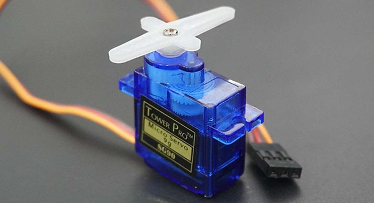
Servo motors are highly specialized electric motors designed for precise control of position, velocity, and torque in CNC (Computer Numerical Control) machines and other precision engineering applications. They are the driving force behind the accurate movement of a CNC machine’s axes (e.g., X, Y, Z) or components in robotic systems, ensuring that tools or workpieces are positioned exactly as programmed. Unlike standard motors, servo motors operate within a closed-loop control system, utilizing feedback devices like encoders or resolvers to continuously monitor and adjust their performance to match the CNC system’s instructions. This precision and adaptability make servo motors indispensable for tasks requiring exact movements and dynamic control in industries ranging from manufacturing to robotic
Servo motors are engineered with specific characteristics that enable their use in high-precision applications. Below are the key features that define their functionality and distinguish them from other motor types, such as spindle motors:
Closed-Loop Control
Servo motors operate in a closed-loop system, meaning they receive continuous feedback from sensors (e.g., encoders or resolvers) to monitor their actual position, speed, and torque. This feedback is compared to the desired values from the CNC control system, and any discrepancies are corrected in real-time by adjusting the motor’s output. This closed-loop control ensures exceptional accuracy, making servo motors ideal for applications where even minor deviations can affect quality, such as CNC machining or robotic arm positioning.
High Precision
Servo motors are capable of micro-adjustments, allowing for precise positioning down to fractions of a millimeter or degree. This precision is critical for tasks like milling complex geometries, drilling precise holes, or positioning tools in multi-axis CNC machines. For example, in a 5-axis CNC machine, servo motors ensure that each axis moves accurately to create intricate parts for aerospace or medical applications.
Variable Speed and Torque
Servo motors can operate across a wide range of speeds and deliver consistent torque, making them versatile for dynamic applications. They can accelerate, decelerate, or stop quickly while maintaining precise control, which is essential for tasks requiring rapid changes in motion, such as contouring or threading in CNC machining. This flexibility allows servo motors to adapt to varying loads and machining requirements.
Compact Design
Servo motors are typically compact and lightweight, designed to fit within the constrained spaces of CNC machines or robotic systems. Their small size enables dynamic, multi-axis motion without adding excessive weight to the machine’s moving components. This is particularly important for high-speed applications where minimizing inertia is critical for responsiveness and accuracy.
Types of Servo Motors
Servo motors come in several variants, each suited to specific applications:
AC Servo Motors: Powered by alternating current, these motors are robust and commonly used in industrial CNC machines for their high power and durability. They are often paired with Variable Frequency Drives (VFDs) for precise control.
DC Servo Motors: Powered by direct current, these motors are simpler and often used in smaller or less demanding applications, such as hobbyist CNC setups. Brushed DC servo motors are less common due to maintenance needs, while brushless versions are preferred for efficiency.
Brushless DC Servo Motors: These combine the benefits of DC motors with improved durability and efficiency, eliminating the need for brushes. They are widely used in modern CNC machines for their low maintenance and high performance.
| Servo Motor Type | Description | Pros | Cons | Applications | Key Characteristics |
| AC Servo Motors | Powered by alternating current, these robust motors are designed for high-power industrial applications, often paired with Variable Frequency Drives (VFDs) for precise speed and torque control. | High power output, excellent durability for continuous operation, precise control with VFDs, suitable for heavy-duty tasks. | Higher cost due to motor and VFD complexity, larger footprint, requires complex setup and programming. | Industrial CNC machines, large-scale milling, drilling, robotics, and automation in automotive/aerospace industries. | High torque at low speeds, robust construction, wide speed range (1,000–6,000 RPM), typically 1–20 kW power rating. |
| DC Servo Motors | Powered by direct current, these motors are simpler and used in smaller or less demanding applications. Available in brushed or brushless configurations, with brushed being less common due to maintenance needs. | Cost-effective, lightweight, simple control systems, suitable for low-power applications. | Limited power output, brushed versions have high maintenance (brush wear), prone to overheating in prolonged use. | Hobbyist CNC setups, small desktop routers, simple automation tasks, low-power applications like PCB milling or light engraving. | Lower torque, speed range of 2,000–10,000 RPM, power ratings typically 0.1–1 kW, less durable than AC motors. |
| Brushless DC Servo Motors | A subset of DC motors, these use electronic commutation instead of brushes, offering improved efficiency and durability. Widely used in modern CNC systems for their balance of performance and low maintenance. | High efficiency, low maintenance, longer lifespan, compact design, good performance across a wide speed range. | Higher initial cost than brushed DC motors, requires electronic controllers, less power than AC servo motors for heavy tasks. | Modern CNC routers, precision robotics, 3D printers, medical equipment, and applications requiring high reliability and precision. | High efficiency (up to 90%), speed range of 3,000–15,000 RPM, power ratings of 0.5–5 kW, low heat generation. |
Role in CNC Machines
In CNC systems, servo motors are primarily responsible for controlling the linear or rotary motion of the machine’s axes. For example:
In a CNC router, servo motors drive the X, Y, and Z axes to position the spindle or cutting tool accurately over the workpiece.
In a CNC lathe, a servo motor may control the rotation of the workpiece (acting as a spindle in some cases) or the movement of the cutting tool.
In multi-axis machines, servo motors enable complex movements, such as tilting or rotating the workpiece or tool in 4- or 5-axis configurations.
Their ability to provide precise, repeatable motion makes servo motors essential for maintaining tight tolerances and achieving high-quality finishes in applications like aerospace, automotive, and medical device manufacturing. By integrating with the CNC machine’s control system, servo motors translate programmed G-code instructions into physical movements, ensuring the machine follows the desired toolpath with minimal error.
Practical Considerations
When selecting or using servo motors in CNC applications, consider the following:
Feedback System: Ensure the motor’s feedback device (e.g., encoder resolution) meets the precision requirements of your application.
Power and Torque: Match the motor’s power and torque to the load and speed requirements of the CNC machine’s axes.
Control System Compatibility: Verify that the servo motor is compatible with the machine’s controller, such as a PLC or CNC software, to ensure seamless integration.
Maintenance: Regularly inspect feedback devices, wiring, and connections to prevent performance issues or electrical faults.
By leveraging the precision, control, and versatility of servo motors, CNC operators can achieve exceptional accuracy and efficiency in their machining processes, making these motors a cornerstone of modern precision engineering.
Click here to buy spindle motors on Amazon.
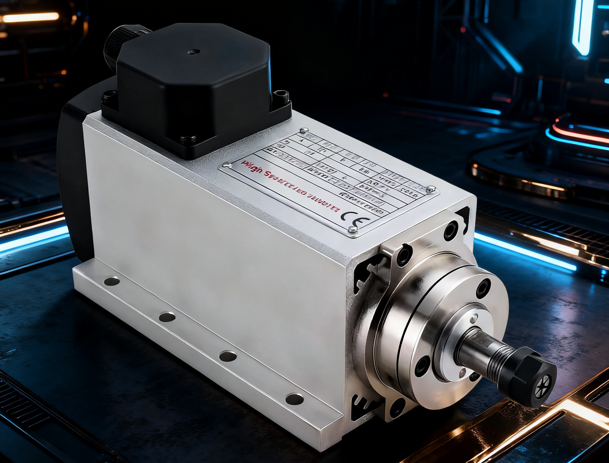
Spindle motors are specialized electric motors engineered to drive the cutting, milling, drilling, or engraving processes in CNC (Computer Numerical Control) machines by rotating cutting tools or workpieces at high speeds. As the powerhouse of CNC systems, spindle motors provide the rotational force and power needed to remove material from workpieces, making them critical for achieving the desired shape, finish, and accuracy in machining tasks. Unlike servo motors, which focus on precise positional control, spindle motors are optimized for continuous, high-speed rotation to deliver consistent power to the tool or workpiece. They are designed to handle a wide range of materials, from soft woods to hard metals, and are integral to applications in industries such as manufacturing, woodworking, and metalworking
Key Features of Spindle Motors
Spindle motors are built with specific characteristics that enable them to excel in machining tasks requiring high rotational speeds and robust power delivery. Below are the key features that define their functionality and distinguish them from other motor types, such as servo motors:
High-Speed Rotation
Spindle motors are designed to operate at high revolutions per minute (RPM), typically ranging from 6,000 to 60,000 RPM or higher, depending on the application. This high-speed capability allows them to perform tasks like engraving, micro-milling, or high-speed cutting, where rapid tool rotation is essential for precision and smooth finishes. For example, a spindle motor running at 24,000 RPM is ideal for engraving intricate designs on metal or plastic, while lower speeds (6,000–12,000 RPM) suit heavier cutting tasks like milling steel.
Power Delivery
The primary focus of spindle motors is to deliver sufficient torque and power to remove material effectively during machining. Available in a range of power ratings (0.5–15 kW or 0.67–20 HP), spindle motors are selected based on the material’s hardness and the machining task’s intensity. High-power spindles provide the torque needed for cutting dense materials like titanium, while lower-power spindles suffice for softer materials like wood or foam. This focus on power delivery ensures consistent performance under varying loads.
Open-Loop or Closed-Loop Control
Many spindle motors operate in open-loop systems, where speed is controlled by a Variable Frequency Drive (VFD) without continuous feedback. This is sufficient for applications where precise rotational speed is more critical than exact positioning. However, advanced spindles may use closed-loop control with feedback devices (e.g., encoders) to maintain consistent speed under varying loads, improving performance in high-precision tasks. Open-loop systems are simpler and more cost-effective, while closed-loop systems offer greater accuracy for demanding applications.
Cooling Systems
Spindle motors generate significant heat during prolonged operation, especially at high speeds or under heavy loads. To manage this, they are equipped with cooling systems:
Air-Cooled: Use fans or ambient air to dissipate heat, suitable for intermittent or medium-duty tasks like woodworking. They are simpler and more affordable but less effective for continuous operation.
Water-Cooled: Use liquid coolant to maintain optimal temperatures, ideal for high-speed or long-duration tasks like metal engraving. They offer superior heat dissipation and quieter operation but require additional maintenance for coolant systems. Effective cooling prevents thermal expansion, protects internal components, and extends motor lifespan.
Tool Compatibility
Spindle motors are equipped with tool holders, such as ER collets, BT, or HSK systems, to secure cutting tools like end mills, drills, or engraving bits. The tool holder type determines the range of tools the spindle can accommodate and affects machining precision and rigidity. For example, ER collets are versatile for general-purpose CNC routers, while HSK holders are preferred for high-speed, industrial applications due to their secure clamping and balance. Compatibility with the CNC machine’s tool change system is also critical for efficient operation.
Role in CNC Machines
In CNC systems, spindle motors are responsible for rotating the cutting tool or, in some cases, the workpiece to perform machining operations. For example:
In a CNC router, the spindle motor rotates a cutting tool to carve patterns in wood or plastic.
In a CNC milling machine, it drives an end mill to remove material from metal workpieces, creating complex geometries.
In a CNC lathe, a spindle motor may rotate the workpiece against a stationary cutting tool for turning operations. Their ability to maintain consistent speed and power ensures high-quality surface finishes and efficient material removal, making them essential for tasks ranging from heavy-duty milling to delicate engraving.
Practical Considerations
When selecting or using spindle motors in CNC applications, consider the following:
Speed and Power Requirements: Match the spindle’s RPM and power rating to the material and task (e.g., high-speed for engraving, high-torque for metal cutting).
Cooling Needs: Choose air-cooled spindles for cost-effective, intermittent use or water-cooled spindles for continuous, high-speed operations.
Tool Holder Compatibility: Ensure the spindle’s tool holder supports the required tools and is compatible with the machine’s setup.
Maintenance: Regularly clean the spindle, monitor cooling systems, and inspect bearings to prevent overheating, vibration, or belt slackening issues.
By leveraging the high-speed rotation, robust power delivery, and specialized design of spindle motors, CNC operators can achieve efficient material removal and high-quality results across a wide range of machining applications, complementing the precise motion control provided by servo motors.
Key Differences Between Servo Motors and Spindle Motors
Servo motors and spindle motors are both critical components in CNC (Computer Numerical Control) machines, but they serve distinct purposes, with designs and performance characteristics tailored to their specific roles. While servo motors excel in precise motion control for positioning machine components, spindle motors are optimized for high-speed rotation to drive cutting or machining processes. Understanding their differences across key factors—primary function, control system, speed and torque, applications, design and construction, power requirements, and feedback mechanisms—is essential for selecting the right motor for your CNC system and optimizing performance. Below, we compare these two motor types in detail, followed by practical examples to illustrate their roles in CNC machines.
1. Primary Function
Servo Motors: Servo motors are designed to control the position, velocity, and movement of machine components with high precision. In CNC machines, they drive the linear or rotary motion of the machine’s axes (e.g., X, Y, Z), positioning the tool head or workpiece accurately according to programmed instructions. Their primary focus is on precise motion control rather than raw power delivery.
Spindle Motors: Spindle motors are engineered to rotate cutting tools or workpieces at high speeds to perform machining tasks such as cutting, milling, drilling, or engraving. They focus on delivering the power and speed needed for material removal or shaping, prioritizing rotational performance over positional accuracy.
Key Difference: Servo motors control the positioning and movement of machine components, while spindle motors drive the rotational force for machining processes.
2. Control System
Servo Motors: Operate in a closed-loop control system, using feedback devices like encoders or resolvers to monitor position, speed, and torque in real time. The CNC controller compares the motor’s actual performance to the desired values and adjusts the input to correct any deviations, ensuring high accuracy and repeatability.
Spindle Motors: Typically use open-loop control systems, where speed is regulated by a Variable Frequency Drive (VFD) without continuous feedback. High-end spindle motors may incorporate closed-loop control with encoders for precise speed regulation under varying loads, but this is less common and not focused on positional control.
Key Difference: Servo motors rely on closed-loop control for precise positioning, while spindle motors often use simpler open-loop systems for speed regulation, with closed-loop options for advanced applications.
3. Speed and Torque
Servo Motors: Offer variable speed and high torque, particularly at low speeds, making them ideal for dynamic movements requiring rapid acceleration and deceleration. They typically operate at lower RPMs (e.g., 1,000–6,000 RPM) compared to spindle motors, prioritizing control over speed.
Spindle Motors: Designed for high-speed rotation, with RPMs ranging from 6,000 to 60,000 or higher, depending on the application. They provide consistent torque optimized for cutting or grinding, with performance tailored to maintain speed under load rather than precise positional adjustments.
Key Difference: Servo motors prioritize high torque at lower speeds for precise motion, while spindle motors focus on high RPMs with consistent torque for machining tasks.
4. Applications
Servo Motors: Used for axis motion in CNC machines, robotics, 3D printers, and automated systems where precise positioning is critical. Examples include moving the tool head in a CNC router, controlling the Z-axis in a milling machine, or driving robotic arms in automated assembly lines.
Spindle Motors: Employed in machining processes such as milling, drilling, engraving, and turning, where the primary task is material removal or shaping. They are found in CNC routers, milling machines, lathes, and engravers, driving tools for applications like woodworking, metalworking, or PCB manufacturing.
Key Difference: Servo motors are used for precise axis movement in CNC and automation systems, while spindle motors drive the cutting or shaping processes in machining applications.
5. Design and Construction
Servo Motors: Compact and lightweight, designed for rapid acceleration and deceleration in multi-axis systems. They incorporate integrated feedback devices (e.g., encoders) and are built to minimize inertia for responsive motion. Their construction prioritizes precision and dynamic performance.
Spindle Motors: Larger and more robust, built to withstand high rotational speeds and sustained loads during machining. They include cooling systems (air-cooled or water-cooled) to manage heat and tool holders (e.g., ER collets, BT, HSK) to secure cutting tools, emphasizing durability and power delivery.
Key Difference: Servo motors are compact for dynamic, precise motion, while spindle motors are robust with cooling systems and tool holders for high-speed machining.
6. Power Requirements
Servo Motors: Typically require lower power, with ratings ranging from a few watts to several kilowatts (e.g., 0.1–5 kW), depending on the application. They are designed for motion control tasks that demand less raw power but high precision.
Spindle Motors: Have higher power ratings, typically 0.5 kW to 15 kW or more (0.67–20 HP), to drive heavy cutting tasks on materials like metal, wood, or composites. Their power requirements reflect the need for significant energy to remove material efficiently.
Key Difference: Servo motors use lower power for motion control, while spindle motors require higher power for material removal and machining.
7. Feedback Mechanism
Servo Motors: Always include feedback mechanisms, such as encoders or resolvers, to provide real-time data on position, speed, and torque. This feedback ensures precise control and error correction, critical for maintaining tight tolerances in CNC operations.
Spindle Motors: May or may not include feedback mechanisms. Many operate without feedback in open-loop systems, relying on VFDs for speed control. Advanced spindles may use encoders for closed-loop speed regulation, but positional feedback is typically unnecessary since their role is rotational, not positional.
Key Difference: Servo motors always use feedback for precise control, while spindle motors often rely on open-loop systems, with feedback optional for specific applications.
Practical Examples in CNC Machines
To illustrate the complementary roles of servo and spindle motors, consider their functions in a typical CNC milling machine:
Servo Motors: Control the movement of the machine’s table or tool head along the X, Y, and Z axes. For example, servo motors position the tool head precisely over a metal workpiece, following the programmed toolpath to ensure accurate cuts. In a 5-axis CNC machine, servo motors handle complex angular movements, enabling intricate geometries.
Spindle Motor: Rotates the milling cutter at high speeds (e.g., 20,000 RPM) to remove material from the workpiece. The spindle motor delivers the power and speed needed to mill metal, ensuring efficient material removal and a smooth surface finish.
Example Scenario: When milling a metal aerospace component, servo motors move the tool head to precise coordinates along multiple axes, ensuring the cutter follows the correct path. Simultaneously, the spindle motor spins the cutting tool at 20,000 RPM to remove material, with its speed controlled by a VFD to match the material’s properties and cutting requirements. Together, these motors enable the machine to produce a complex, high-precision part.
Choosing Between Servo and Spindle Motors
Selecting the appropriate motor for a CNC (Computer Numerical Control) system or precision engineering application requires understanding the distinct roles of servo motors and spindle motors. Each motor type is designed for specific functions within a CNC machine, with servo motors excelling in precise positional control and spindle motors optimized for high-speed rotation and material removal. In most CNC systems, these motors are not mutually exclusive but work together to achieve accurate and efficient machining. The choice between servo and spindle motors—or the decision to integrate both—depends on the specific requirements of your application, including the type of task, material, precision needs, and system configuration. Below, we outline key considerations for choosing between servo and spindle motors and explain how they are typically used together in CNC machines.
Choosing Servo Motors
Servo motors are the ideal choice when your application demands precise control over position, velocity, and torque. Their closed-loop control systems, which rely on feedback devices like encoders or resolvers, ensure accurate and repeatable movements, making them essential for tasks requiring dynamic motion control.
When to Choose Servo Motors:
CNC Axis Movement: Servo motors are used to drive the X, Y, Z, or additional axes (e.g., A, B in 5-axis machines) in CNC systems, positioning the tool head or workpiece with high precision. For example, in a CNC router, servo motors move the gantry to exact coordinates for cutting or engraving.
Robotics: In robotic arms, servo motors control joint movements, enabling precise manipulation for tasks like assembly, welding, or pick-and-place operations.
Automation Systems: Servo motors are used in automated machinery, such as 3D printers or conveyor systems, where precise positioning or speed control is critical.
Applications Requiring Micro-Adjustments: Tasks like threading, contouring, or multi-axis machining benefit from servo motors’ ability to make fine positional adjustments.
Key Considerations:
Precision Needs: Choose servo motors with high-resolution encoders (e.g., 10,000 pulses per revolution) for applications requiring tight tolerances, such as aerospace or medical device manufacturing.
Torque and Speed: Ensure the servo motor’s torque and speed ratings match the load and dynamic requirements of the machine’s axes. For example, heavier workpieces may require higher-torque motors.
Control System Compatibility: Verify that the servo motor is compatible with your CNC controller or PLC, ensuring seamless integration with the machine’s software.
Maintenance: Plan for regular inspection of feedback devices and electrical connections to prevent performance issues, such as encoder misalignment or wiring faults.
Example: In a 5-axis CNC milling machine, servo motors position the tool head and workpiece with sub-millimeter accuracy, enabling complex geometries for aerospace components.
Choosing Spindle Motors
Spindle motors are the go-to choice when your application focuses on high-speed rotation to drive cutting, drilling, or engraving processes. These motors are designed to deliver consistent power and speed for material removal, making them critical for machining tasks across various materials.
When to Choose Spindle Motors:
Cutting and Milling: Spindle motors drive cutting tools like end mills or router bits to remove material from wood, metal, plastic, or composites in CNC routers and milling machines.
Drilling: They rotate drill bits at high speeds to create precise holes in materials, such as steel or aluminum, for automotive or machinery parts.
Engraving: High-speed spindle motors are used for detailed work, such as etching designs on jewelry, signage, or printed circuit boards (PCBs).
Turning: In CNC lathes, spindle motors rotate the workpiece against a stationary tool to shape cylindrical parts, such as shafts or fittings.
Key Considerations:
Material and Task: Select a spindle motor with sufficient power (e.g., 0.5–15 kW) and speed (e.g., 6,000–60,000 RPM) for the material and task. For example, high-power, water-cooled spindles are ideal for metal cutting, while air-cooled spindles suit woodworking.
Cooling System: Choose air-cooled spindles for intermittent tasks or water-cooled spindles for continuous, high-speed operations to manage heat effectively.
Tool Holder Compatibility: Ensure the spindle’s tool holder (e.g., ER collets, HSK) supports the required tools and is compatible with the machine’s tool change system.
Maintenance: Regularly clean the spindle, monitor cooling systems, and lubricate bearings to prevent issues like belt slackening or electrical short circuits.
Example: In a CNC router, a 3 kW water-cooled spindle motor rotates a router bit at 24,000 RPM to carve intricate patterns in hardwood for furniture production.
Combined Use in CNC Machines
In most CNC machines, servo motors and spindle motors are used together, leveraging their complementary strengths to achieve precise and efficient machining:
Servo Motors for Motion Control: Servo motors position the tool head or workpiece along the machine’s axes, ensuring the cutting tool follows the programmed toolpath with high accuracy. For example, they move the gantry in a CNC router or adjust the tool angle in a 5-axis machine.
Spindle Motors for Machining: Spindle motors rotate the cutting tool or workpiece at the required speed and power to perform material removal, ensuring efficient cutting, drilling, or engraving.
Example Scenario: In a CNC milling machine, servo motors drive the X, Y, and Z axes to position a metal workpiece under the tool head, while a spindle motor spins an end mill at 20,000 RPM to remove material, creating a precise component. The servo motors ensure the tool follows the correct path, while the spindle motor delivers the power needed for cutting.
Maintenance Considerations
Proper maintenance of servo and spindle motors is critical to ensuring the reliability, precision, and longevity of CNC (Computer Numerical Control) machines. Both motor types serve distinct roles—servo motors for precise axis positioning and spindle motors for high-speed material removal—but they require regular care to prevent issues like wear, overheating, or electrical faults, including short circuits or belt slackening. By implementing targeted maintenance practices, operators can minimize downtime, maintain machining accuracy, and extend the lifespan of these critical components. Below, we outline specific maintenance considerations for servo motors and spindle motors, detailing actionable steps to keep them in optimal condition.
Servo Motors
Servo motors, responsible for precise positional control in CNC machines, rely on closed-loop systems with feedback devices to maintain accuracy. Regular maintenance ensures their performance remains consistent, preventing issues that could compromise axis movement or machining precision.
Regularly Check and Calibrate Feedback Devices (e.g., Encoders)
Servo motors use feedback devices like encoders or resolvers to monitor position, speed, and torque in real time. Misalignment, dirt, or wear in these devices can lead to inaccurate positioning or control errors.
Actions:
Inspect encoders or resolvers for dust, debris, or physical damage that could interfere with signal accuracy. Clean with a lint-free cloth and non-corrosive cleaner.
Calibrate feedback devices periodically using manufacturer-provided software or tools to ensure alignment with the CNC controller.
Check encoder cables for wear or loose connections, as poor signal transmission can cause positioning errors.
Frequency: Inspect and clean every 3–6 months or 500–1,000 operating hours; calibrate as per manufacturer guidelines, typically annually or after major maintenance.
Benefits: Maintains positional accuracy, prevents control errors, and ensures consistent performance in tasks like multi-axis machining or robotics.
Inspect for Wear in Bearings and Lubricate as Needed
Bearings in servo motors reduce friction during rapid axis movements, but wear can lead to increased vibration, noise, or reduced precision. Proper lubrication minimizes wear and maintains smooth operation.
Actions:
Listen for unusual noises (e.g., grinding or humming) or use a vibration analyzer to detect bearing wear. Excessive vibration indicates the need for inspection or replacement.
Apply the manufacturer-recommended lubricant (e.g., grease or oil) to bearings, ensuring not to over-lubricate, which can attract debris or cause heat buildup. Some servo motors use sealed bearings that require no lubrication but should be checked for wear.
Replace worn bearings promptly to prevent damage to the motor shaft or rotor.
Frequency: Inspect bearings every 6 months or 1,000 operating hours; lubricate per manufacturer specifications, typically every 500–1,000 hours for non-sealed bearings.
Benefits: Reduces friction, prevents vibration-induced damage, and extends motor lifespan.
Monitor Electrical Connections to Prevent Signal Loss or Interference
Servo motors rely on stable electrical connections for power and signal transmission to the controller and feedback devices. Loose, corroded, or damaged connections can cause signal loss, interference, or electrical faults like short circuits.
Actions:
Inspect power and signal cables for fraying, corrosion, or loose terminals. Tighten connections and replace damaged cables.
Use a multimeter to check for consistent voltage and continuity in wiring to ensure reliable power delivery.
Shield signal cables from electromagnetic interference (EMI) by routing them away from high-power components like spindle motors or VFDs.
Frequency: Check connections monthly or every 500 operating hours; perform detailed inspections during routine maintenance cycles.
Benefits: Prevents signal loss, reduces the risk of electrical faults, and ensures reliable communication with the CNC controller.
Spindle Motors
Spindle motors, designed for high-speed rotation and material removal, require maintenance to manage heat, vibration, and tool-related issues. Proper care prevents performance degradation and costly failures, such as electrical short circuits or mechanical damage.
Clean Tool Holders and Collets to Prevent Tool Runout
Tool holders (e.g., ER collets, BT, HSK) and collets secure cutting tools to the spindle. Dirt, debris, or damage can cause tool runout (wobbling), leading to poor machining quality, increased vibration, or stress on the spindle.
Actions:
Clean tool holders and collets after each tool change using a lint-free cloth and non-corrosive cleaner to remove coolant residue, chips, or dust.
Inspect for wear, dents, or scratches on the tool holder’s taper or collet, which can cause misalignment. Replace damaged components immediately.
Use a dial indicator to measure tool runout after installation; runout exceeding 0.01 mm indicates a problem requiring correction.
Frequency: Clean after every tool change or daily during heavy use; inspect for wear monthly or every 500 operating hours.
Benefits: Maintains machining precision, reduces vibration, and prevents premature wear on the spindle and tools.
Maintain Cooling Systems (Air or Water) to Prevent Overheating
Spindle motors generate significant heat during high-speed or prolonged operation, requiring effective cooling to prevent overheating, which can lead to insulation degradation or component failure.
Actions:
For Air-Cooled Spindles: Clean cooling fins and fans regularly to remove dust or debris that obstructs airflow. Ensure vents are clear to maintain cooling efficiency.
For Water-Cooled Spindles: Monitor coolant levels in the reservoir, topping up with the manufacturer-recommended fluid. Inspect hoses, fittings, and the cooling jacket for leaks or corrosion. Flush the system every 6–12 months to remove sediment or algae.
Use thermal imaging to detect hot spots, indicating cooling system inefficiencies or potential faults.
Frequency: Check air-cooled systems weekly; monitor water-cooled systems weekly for coolant levels and monthly for leaks; flush water-cooled systems every 6–12 months.
Benefits: Prevents overheating, reduces thermal stress on windings and bearings, and extends spindle lifespan.
Monitor Bearings for Vibration or Noise, Indicating Potential Wear
Spindle motor bearings, often ceramic or steel, support high-speed rotation. Wear or imbalance can cause excessive vibration or noise, leading to reduced precision, belt slackening, or motor damage.
Actions:
Listen for abnormal noises (e.g., grinding, rattling) during operation, indicating bearing wear or misalignment.
Use a vibration analyzer to measure bearing vibration levels, comparing them to manufacturer baselines to detect issues early.
Lubricate bearings per manufacturer guidelines (if not sealed), using the specified grease or oil. Replace worn bearings promptly to prevent damage to the spindle shaft or rotor.
Frequency: Monitor vibration and noise daily or weekly during operation; perform detailed bearing checks every 3–6 months or 500–1,000 operating hours.
Benefits: Prevents mechanical failures, maintains machining accuracy, and reduces the risk of costly repairs.
Conclusion
Servo motors and spindle motors are indispensable components in CNC (Computer Numerical Control) machines and precision engineering systems, each playing a complementary but distinct role that drives the overall functionality of these systems. Servo motors excel in delivering precise motion control, enabling accurate positioning of machine axes or components in applications like CNC machining, robotics, and automation. In contrast, spindle motors are engineered for high-speed, high-power rotation, providing the force needed to drive cutting tools or workpieces for tasks such as milling, drilling, or engraving. By understanding their key differences—control systems, applications, design, speed and torque characteristics, power requirements, and feedback mechanisms—operators can make informed decisions to optimize CNC performance and achieve high-quality results.
The synergy between servo and spindle motors is what makes CNC machines so versatile and effective. Servo motors ensure that the tool head or workpiece is positioned with pinpoint accuracy, while spindle motors deliver the rotational power necessary for efficient material removal or shaping. For example, in a CNC milling machine, servo motors control the X, Y, and Z axes to follow a precise toolpath, while a spindle motor rotates the cutting tool at high speeds to produce a smooth, accurate part. Proper selection and maintenance of both motor types are critical to avoiding issues like belt slackening, electrical short circuits, or mechanical failures, ensuring consistent precision and reliability.
For those building, upgrading, or operating CNC systems, carefully consider the specific demands of your application—such as material type, precision requirements, and duty cycle—when choosing servo and spindle motors. Select servo motors with appropriate torque, feedback resolution, and controller compatibility for precise axis control, and choose spindle motors with the right power, speed, and cooling system to match your machining tasks. Regular maintenance, including cleaning, lubrication, feedback device calibration for servo motors, and cooling system care for spindle motors, is essential to maintain performance and extend motor lifespan. By leveraging the complementary strengths of servo and spindle motors and implementing proactive maintenance, you can achieve exceptional results in machining and automation tasks, ensuring efficiency, precision, and durability in your CNC operations.
Click here to download Zhong Hua Jiang's Catalogue.
 Zhong Hua Jiang Catalogue 2025.pdf
 English
 简体中文
简体中文 繁體中文
繁體中文 العربية
 Français
 Русский
 Español
 Português
 Deutsch
 italiano
 日本語
日本語 한국어
한국어 Nederlands
 Tiếng Việt
 ไทย
ไทย Polski
 Türkçe
 አማርኛ
አማርኛ ພາສາລາວ
 ភាសាខ្មែរ
 Bahasa Melayu
 ဗမာစာ
ဗမာစာ தமிழ்
தமிழ் Filipino
 Bahasa Indonesia
 magyar
 Română
 Čeština
 Монгол
 қазақ
қазақ Српски
 हिन्दी
 فارسی
فارسی Kiswahili
 Slovenčina
 Slovenščina
 Norsk
Norsk Svenska
 українська
 Ελληνικά
 Suomi
Suomi Հայերեն
 עברית
עברית Latine
 Dansk
Dansk اردو
اردو Shqip
Shqip বাংলা
বাংলা Hrvatski
 Afrikaans
 Gaeilge
 Eesti keel
 Māori
Māori සිංහල
සිංහල नेपाली
 Oʻzbekcha
 latviešu
 অসমীয়া
 Aymara
 Azərbaycan dili
 Bamanankan
 Euskara
 Беларуская мова
 भोजपुरी
 Bosanski
 Български
 Català
 Cebuano
 Corsu
Corsu ދިވެހި
 डोग्रिड ने दी
 Esperanto
 Eʋegbe
 Frysk
Frysk Galego
 ქართული
 guarani
 ગુજરાતી
 Kreyòl ayisyen
 Hausa
Hausa ʻŌlelo Hawaiʻi
 Hmoob
Hmoob íslenska
 Igbo
Igbo Ilocano
 Basa Jawa
 ಕನ್ನಡ
ಕನ್ನಡ Kinyarwanda
 गोंगेन हें नांव
 Krio we dɛn kɔl Krio
 Kurdî
Kurdî Kurdî
Kurdî Кыргызча
 Lingala
 Lietuvių
 Oluganda
 Lëtzebuergesch
 Македонски
 मैथिली
 Malagasy
 മലയാളം
 Malti
Malti मराठी
मराठी ꯃꯦꯇꯥꯏ (ꯃꯅꯤꯄꯨꯔꯤ) ꯴.
 Mizo tawng
 Chichewa
 ଓଡ଼ିଆ
ଓଡ଼ିଆ Afaan Oromoo
 پښتو
پښتو ਪੰਜਾਬੀ
 Runasimi
 Gagana Samoa
 संस्कृत
 Gaelo Albannach
 Sepeti
 Sesotho
 chiShona
 سنڌي
سنڌي Soomaali
 Basa Sunda
 Wikang Tagalog
 Тоҷикӣ
 Татарча
 తెలుగు
 ትግንያውያን
 Xitsonga
 Türkmençe
 संस्कृत
 ئۇيغۇرچە
 Cymraeg
 isiXhosa
 ייִדיש
 Yorùbá
 isiZulu


