You are here:Home » News » What Is A CNC Router And How Does It Work?
What Is A CNC Router And How Does It Work?
Views: 0 Author: Site Editor Publish Time: 2026-07-30 Origin: Site
Have you ever wished your designs could turn into perfect parts without guesswork? Searching for a CNC Router usually means you want faster repeatability and cleaner results.
This guide explains what a CNC Router is and how it works in real life. You’ll learn about X/Y/Z movement, the spindle, and G-code that drives the cutting.
In this post, you’ll learn what a CNC Router can and can’t do, plus how to plan your first job step by step.
CNC Router Definition — What Is a CNC Router?
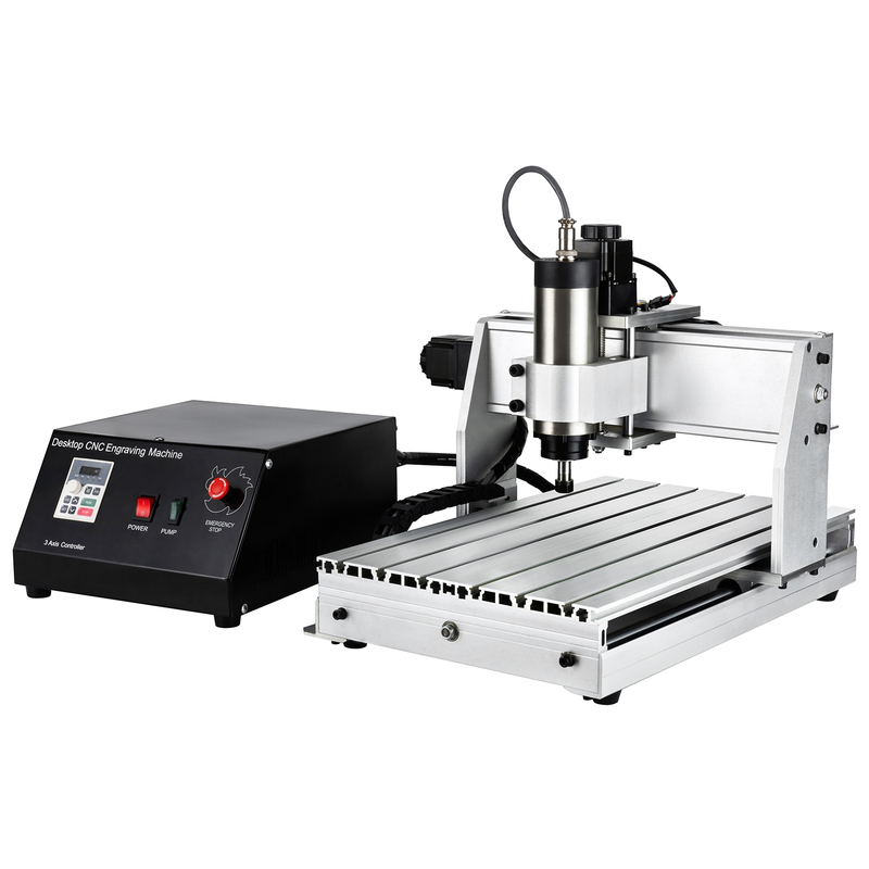
A CNC Router is a computer-controlled cutting machine that follows a precise program. In plain English, it moves a spinning cutting tool along exact paths. It does this using commands the machine can “read” and execute.
Most projects use subtractive manufacturing. That means it starts from a larger piece of material, then removes what isn’t needed. The removed material becomes the shape you designed.
Here’s what a CNC Router typically handles well in real shops. People use it for jobs where clean edges and repeatable results matter.
Cutting sheet goods into parts
Engraving details and text
Carving logos, shapes, decorative patterns
Milling light materials like wood, acrylic, MDF, plastics
CNC Router vs CNC Mill (Quick Comparison)
A CNC Router often wins on cost and speed for softer or sheet materials. It is designed for materials that carve easily with the right spindle speed and bits. That’s why you’ll see routers in sign shops, schools, hobby production lines, and light industrial work.
CNC mills are built for heavier cutting forces. They typically have higher rigidity and are better matched to harder metals. When steel enters the picture, a mill’s design usually handles the workload more safely and accurately.
Use this quick rule of thumb when planning your purchase or workflow.
Rule of thumb
CNC Router = great for wood / plastics / soft metals
CNC mill = better for harder metals / steel
Below is a simple comparison you can use during early discussions.
Feature
CNC Router
CNC Mill
Typical materials
Wood, acrylic, MDF, plastics; soft metals
Hard metals like steel; demanding metal work
Rigidity focus
Built for lighter duty, often faster work
Built for higher stiffness and heavy cutting
Best fit jobs
Signs, engraving, carving, light milling
Hard metal machining, tighter metal operations
Budget feel
Often lower-cost entry
Usually higher cost due to build and capability
In day-to-day terms, routers help teams ship prototypes faster. Mills help teams avoid stress, chatter, and tool strain when cutting harder materials.
What Makes a CNC Router Different from a Handheld Router?
A handheld router is guided by a person. A CNC Router is guided by a computer system. That one change is why repeatable parts become realistic.
A CNC router runs on computer-driven motion. It uses a program called G-code to control where the spindle goes next. The machine follows X/Y/Z movement so the cut matches the design.
Once setup is correct, the process becomes mostly repeatable across runs. The machine doesn’t “get tired” or change pressure mid-job. They still need good setup, but the cutting behavior stays consistent.
It follows G-code instead of human direction
It repeats the same toolpath across multiple parts
It reduces “hand skill” dependency after calibration
It supports complex shapes through planned toolpaths
From the buyer’s perspective, this difference matters for timelines and throughput. Teams can run batches with less rework, especially for engraving, routing outlines, and pocketing features.
How Does a CNC Router Work? (Core Working Principle)
A CNC Router feels simple once you understand its “loop.” It reads a program, moves the axes, spins the spindle, and follows a planned cut path. It doesn’t guess. It executes.
Think of it like a well-rehearsed crew. They still need correct setup, safe tooling, and good settings. But once the run starts, they keep doing the same job the same way across repeats.
The CNC Router “brain”: G-code instructions
The CNC Router “brain” is G-code. This file tells it exactly how and where to move next. It also sets the cutting behavior so the cut looks right instead of messy.
G-code mainly controls three areas:
Movement coordinates: where the tool goes in X/Y/Z space
Spindle speed / cutting behavior: how fast the spindle spins and how it engages
Feed rates and depth: how quickly it cuts and how deep each pass runs
Here’s a quick view of how those instructions map to real actions during a job.
G-code control
What it affects
What you see on the material
Movement coordinates
X/Y/Z paths
Accurate shape lines and pockets
Spindle speed
Cutting speed at the tool
Better surface finish, less tearing
Feed rate & depth
Cut intensity per move
Correct thickness, fewer chatter marks
If those numbers are off, the job doesn’t “mysteriously fail.” It just cuts the wrong way, at the wrong energy, for the wrong material.
The CNC Router “movement”: X/Y/Z axes
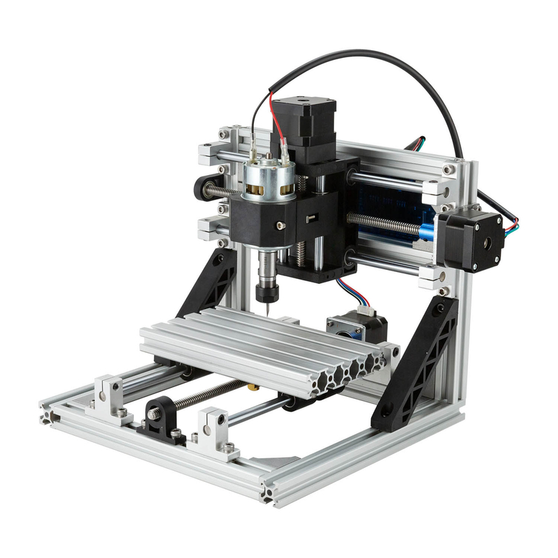
After reading the program, the CNC Router turns it into motion using the X/Y/Z axes. Most common routers run a 3-axis setup, which covers the majority of carving and routing work.
X-axis: left/right movement
Y-axis: front/back movement
Z-axis: up/down depth control
That Z axis is what makes real “machining” possible. It controls how the bit enters the material for pockets, grooves, and clean profiling.
Some CNC Router setups support an upgrade. When a 4th rotary axis is supported, the machine can rotate a workpiece for cylindrical 3D carving. The extra axis lets it follow wrapped shapes instead of only flat planes.
The CNC Router “cutting heart”: spindle + cutting bit
The spindle holds and spins the cutting bit at high speed. During a run, it’s the part doing the physical work. The bit geometry plus spindle speed determines how the material breaks and leaves chips.
Spindle speed matters because it impacts:
Material removal rate: how quickly material is cleared
Finish quality: smoother edges versus rough lines
Tool wear risk: too fast can overheat, too slow can cause dragging
When people struggle, it’s often not the router brand. It’s the mismatch between spindle speed, feed rate, and the bit type. Those three must “agree,” or the cut quality will tell the story immediately.
Cut path execution: toolpath following
Now for the part everyone can picture: the router follows a toolpath. A toolpath is the planned route the bit takes across the job. It includes where the tool travels and where it plunges for depth.
This is the practical way to think about it: the router follows the planned toolpath, not your imagination. It follows coordinates. It follows order. It follows programmed intent.
A correct toolpath usually includes clear strategies like profiling the outer shape, pocketing inside areas, and engraving text with controlled depths. A wrong toolpath can still run. It just runs into clamps, skips features, or creates offsets you didn’t design.
CNC Router Workflow — From Design to Finished Part
A CNC Router workflow is a simple pipeline, but small mistakes cost real time. We go from CAD design to CAM toolpaths, then G-code, setup, running, and finishing. When each step matches the last, parts come out clean and repeatable.
Most teams learn this fast by running a tiny test job first. Chips tell the truth: if the path, depth, and feeds are wrong, you’ll see it immediately.
Step 1 — Create the design in CAD
CAD is where the work starts. It builds the 2D sketch or 3D shape, then locks in dimensions and geometry. People often focus on “the picture,” but the router needs real measurements.
For example, engraving depth depends on your design settings and how you model the relief. Part size and cut lines determine where the bit will enter and where it should avoid edges.
Here’s what good CAD output usually includes for a CNC Router project:
Layout that fits your machine’s effective working area
Step 2 — Use CAM to generate the CNC Router toolpath
CAM is the translator between your design and machine motion. It converts the CAD model into toolpaths and assigns cutting parameters. Those parameters include depth per pass, spindle speed, and feed rate.
You’ll see two benefits from CAM. First, it plans the route so material removal looks controlled. Second, it helps reduce errors by mapping where the tool travels before the job starts.
Some teams use combined CAD/CAM software to keep everything in one workspace. It can save time, especially for signs, engraving, and small prototypes.
This is the typical CAM output you’re aiming for before you export:
Step 3 — Export G-code for the CNC Router controller
After CAM generates toolpaths, it exports G-code. That file becomes the instruction set the CNC Router controller follows. It includes coordinates and machining parameters, so the controller knows where to cut next.
Correct G-code matters because wrong numbers cause wrong cuts. If depth values are off, you’ll either leave material behind or dig too deep. If feed or spindle values don’t match the bit and material, the finish suffers fast.
A useful mindset: treat G-code like a “recipe.” The oven may work, but the recipe must be right.
Step 4 — Machine setup: workholding, tool, and zero point
Setup turns the virtual design into real motion. The CNC Router needs the workpiece secured, the correct tool installed, and the coordinate system aligned.
Common workholding options include:
Clamps on the bed for rigid sheet and panel work
Vacuum hold-down / vacuum seal when applicable to prevent lifting
Then comes zeroing. Zero points align X/Y/Z starting positions to the work origin. If zero is wrong, the whole job runs offset. That’s why many experienced users treat zeroing as a “safety step,” not a formality.
Step 5 — Run the job: program execution and material removal
Now the CNC Router runs the program. The controller sends motion signals to the motors. While the head moves along the planned toolpath, the spindle rotates the cutting bit.
This part feels mechanical, but it’s where results are created. The material removal rate and edge quality come from the match between path, speed, and tool geometry.
Typical operations during one job include:
Profiling the outer shape
Pocketing inside areas
Drilling holes or template features
Engraving text and logos
3D contouring for stepped relief
Step 6 — Finish & remove the part
After machining, chips and dust need attention. A quick cleanup improves safety and prevents debris from mixing into the next job’s setup. Then the part may need light finishing.
Depending on material and cut quality, finishing can be sanding or polishing. For engraved plastics or acrylic, careful cleanup matters because residue can hide the true surface.
Below is a simple view of the final steps and what they’re meant to fix for most CNC Router users.
Post-run step
Why it matters
Typical output
Chip/dust cleanup
Prevents interference and messy surfaces
Clear edges, safer handling
Light sanding/polish
Improves surface feel and appearance
Smoother engraving, cleaner sign faces
Once the part is inspected and handled, the workflow is ready to repeat for the next run.
FAQs About CNC Router
Q: What is a CNC router used for?
A: CNC routers cut, engrave, carve, and drill. They work great on wood, acrylic, MDF, plastics, foam, and PCB prototypes.
Q: What is the difference between a CNC router and a CNC mill?
A: A CNC Router is optimized for softer materials and sheet work. A CNC mill is better for harder metals like steel due to higher rigidity.
Q: Do I need CAD and CAM to use a CNC router?
A: Yes. CAD creates the design, CAM generates toolpaths, and CAM exports G-code for the controller.
Q: What does G-code do on a CNC router?
A: G-code tells the CNC Router where to move using X/Y/Z coordinates. It also sets spindle speed, feed rates, and cutting depth.
Q: Can a CNC router cut metal?
A: Yes for soft metals like aluminum and brass. For thick hardened steel, a different machine solution is usually needed.
Q: How accurate is a CNC router?
A: Accuracy depends on machine build, calibration, and workholding. Repeatability improves when setups are consistent and zeros are correct.
Join us as an exclusive distributor of CNC Router Machines and CNC Spindle Motors. As a professional manufacturer, we provide high-performance machines, attractive profit margins, technical training, and full marketing support. Build a strong partnership with us and expand your market with confidence.


 English
 简体中文
简体中文 繁體中文
繁體中文 العربية
 Français
 Русский
 Español
 Português
 Deutsch
 italiano
 日本語
日本語 한국어
한국어 Nederlands
 Tiếng Việt
 ไทย
ไทย Polski
 Türkçe
 አማርኛ
አማርኛ ພາສາລາວ
 ភាសាខ្មែរ
 Bahasa Melayu
 ဗမာစာ
ဗမာစာ தமிழ்
தமிழ் Filipino
 Bahasa Indonesia
 magyar
 Română
 Čeština
 Монгол
 қазақ
қазақ Српски
 हिन्दी
 فارسی
فارسی Kiswahili
 Slovenčina
 Slovenščina
 Norsk
Norsk Svenska
 українська
 Ελληνικά
 Suomi
Suomi Հայերեն
 עברית
עברית Latine
 Dansk
Dansk اردو
اردو Shqip
Shqip বাংলা
বাংলা Hrvatski
 Afrikaans
 Gaeilge
 Eesti keel
 Māori
Māori සිංහල
සිංහල नेपाली
 Oʻzbekcha
 latviešu
 অসমীয়া
 Aymara
 Azərbaycan dili
 Bamanankan
 Euskara
 Беларуская мова
 भोजपुरी
 Bosanski
 Български
 Català
 Cebuano
 Corsu
Corsu ދިވެހި
 डोग्रिड ने दी
 Esperanto
 Eʋegbe
 Frysk
Frysk Galego
 ქართული
 guarani
 ગુજરાતી
 Kreyòl ayisyen
 Hausa
Hausa ʻŌlelo Hawaiʻi
 Hmoob
Hmoob íslenska
 Igbo
Igbo Ilocano
 Basa Jawa
 ಕನ್ನಡ
ಕನ್ನಡ Kinyarwanda
 गोंगेन हें नांव
 Krio we dɛn kɔl Krio
 Kurdî
Kurdî Kurdî
Kurdî Кыргызча
 Lingala
 Lietuvių
 Oluganda
 Lëtzebuergesch
 Македонски
 मैथिली
 Malagasy
 മലയാളം
 Malti
Malti मराठी
मराठी ꯃꯦꯇꯥꯏ (ꯃꯅꯤꯄꯨꯔꯤ) ꯴.
 Mizo tawng
 Chichewa
 ଓଡ଼ିଆ
ଓଡ଼ିଆ Afaan Oromoo
 پښتو
پښتو ਪੰਜਾਬੀ
 Runasimi
 Gagana Samoa
 संस्कृत
 Gaelo Albannach
 Sepeti
 Sesotho
 chiShona
 سنڌي
سنڌي Soomaali
 Basa Sunda
 Wikang Tagalog
 Тоҷикӣ
 Татарча
 తెలుగు
 ትግንያውያን
 Xitsonga
 Türkmençe
 संस्कृत
 ئۇيغۇرچە
 Cymraeg
 isiXhosa
 ייִדיש
 Yorùbá
 isiZulu